By Mike Mavrigian
Replacing cam bearings in a factory LS block can be easy, or it can turn into a can of worms. Granted, this article likely will not answer all questions or address every possible issue, but we’ll make an honest attempt.
LS CAM BEARING DIFFERENCES
The outside diameter of OEM LS cam bearings differ. In other words, the bores are “stepped” in diameter. Position #1 and #5 bearings are the same size, #2 and #4 bearings are a different size, and the middle #3 bearing is yet another size. This applies to all except the LSX, which features the same size bore of 2.308” in all positions. In terms of potential bearing installation challenges, the stepped approach is not the issue.
Read this article with all images in the digital issue of Engine Professional magazine https://engineprofessional.com/2025EPQ2/#p=48
One of the major points of potential issues involves GM changing the tolerance range of both cam bore and cam journals (some may say haphazardly). In some cases, a tolerance of 0.002″ was used, and in others, 0.004″. When you consider potential stack-up issues between bore size and bearing OD, it’s obvious that serious insufficient or excessive bearing press fits are possible. You won’t find out until you measure due to possible variances in parent cam bore diameters.
How did this occur? After blocks were cast and machined, cam bearings were installed, and then honed to size. This applies to both iron and aluminum blocks. The challenge is when the aftermarket attempts to recondition the blocks, knocking the OE bearings out and replacing with aftermarket bearings, this forces the aftermarket builder to deal with the existing cam bore size.
Luckily, aftermarket bearing makes such as Dura-Bond (to cite but one example), came to the rescue by developing a range of bearings to accommodate too-tight or too-loose factory bores, as well as deviations in cam journal diameters.
Factory LS blocks feature an oil delivery slot and hole in each cam bore. Naturally, the oil hole in the bearing must align with this slot. If dealing with an aftermarket block such as a Dart block, the special Dart bearings feature an oil groove along the outer diameter in addition to an oil hole. Some builders prefer to align the oil hole at the 3-o’clock position to align with the oil hole in the cam bore, while some prefer to orient the oil hole in the 5 to 6 o’clock position. This allows an oil wedge to generate at the 7-o’clock position to better accommodate high valve spring loads. The oil that enters via the bore’s oil hole then travels around the bearing via it’s outside-diameter groove.
UNDER/OVER SIZES
Citing Durabond’s offerings for LS engines as an example, both “cam saver” and “block saver” versions are available for variations of cam tunnel sizes and cam journals as follows:
- CAM SAVERS: 0.001, 0.010, 0.030 under I.D. (for 1999-2006 LS1 first design blocks)
- BLOCK SAVERS: #1 and #5 +0.020 O.D., 2, 3, 4 +0.010 oversize O.D. (for LS1 1999-2006 LS1 first design)
- CAM SAVERS: 0.010, 0.020 under I.D. (for 2003-2009 second design, LS3 and LS7)
- CAM SAVERS: 0.001, 0.002, 0.003, 0.010, 0.020, 0.030 UNDER I.D (for 2007-2018 LS3, LS7, LS9, LSX)
- BLOCK SAVERS: +0.010 O.D., 2.357 Hsg non-stepped (for 2007-2018 LS3, LS7, LS9, LSX)
- BLOCK SAVERS: +0.020 O.D. Hsg stepped (for 2007-2018 LS3, LS7, LS9, LSX)
SPUN CAM BEARINGS?
Some builders have experienced spun cam bearings in various positions. From speaking with several builders who routinely deal with the LS platform, the #3 center bearing appears to be the most common location. The original OE bearing press fit for all positions was listed as 0.001-0.0015″. Considering expansion/contraction, the potential for bearing spin appears to exist. In order to address this, a tighter fit was deemed appropriate. GM aftermarket bearings now call for an interference fit of 0.005-0.008″, which seems to make much more sense and should eliminate the potential for bearing spin.
Cam bores changed as design generations evolved. With the proliferation of LS platforms, if in doubt, measure. If not in doubt, measure. Factory bore sizes can vary. Again, GM bores to accept “thick” bearings, then honed the bearings for cam oil clearance. The parent bores can deviate.
All LS Gen III and early Gen IV blocks feature cam bearings widths of 0.630″, while wider bearings of 0.775″ were used in late Gen IV blocks, providing a larger footprint and aids in camshaft rigidity. Use of the “narrow” bearings provide a bit more leeway and are a tad more forgiving in terms of dealing with bore alignment.
CAM OIL CLEARANCE BASED ON LS TYPE
The maximum cam journal to bearing oil clearance is 0.005″ (0.127mm) with the service bearings on engines that re equipped with AFM (active fuel management) or CMP (camshaft position sensor). On engines without AFM/CMP, maximum oil clearance is 0.006″ (0.152mm). Be aware that OE cam bearing part numbers differ depending on use of the first-design camshaft where the cam sensor was placed at the rear of the block and the second camshaft design where the cam sensor is placed in the timing cover. The following provided by Dura-Bond:
First design camshaft with aluminum blocks and iron blocks up to early 2009:
- Part Number 19260874 – Replaces 19167383, positions #1 and #5. 2005-2013 Gen IV engines with iron block and first design camshaft.
- Part Number 19260875 – Replaces 19167382, position #2 and #4. 2005-2013 Gen IV engine with aluminum block; 2007-2009 Gen IV engines with iron block and first design camshaft.
- Part Number 19260876 – Replaces 19167218, position #3. 2005-2009 Gen IV engines with aluminum block. 2007-2009 Gen IV engines with iron block and first design camshaft.
Second design camshaft with iron block only, late 2009 to present:
- Part Number 19260877 – Replaces 191673383, positions #1 and #5. 2009-1/2 – 2013 Gen IV engines with iron block and second design camshaft.
- Part Number 19260878 – Replaces 19167382, position #2 and #4. 2009-1/2 – 2013 Gen IV engines with iron block and second design camshaft.
- Part Number 19260879 – Replaces 19167218, position #3. 2009-1/2 – 2013 Gen IV engines with iron block and second camshaft design.
COATED BEARINGS
The AERA Technical Committee offers the following information regarding replacement cam bearings. There are two different groups of bearings used which can be categorized as early engines up to mid-year 2009 and late engines which are late 2009 and later.
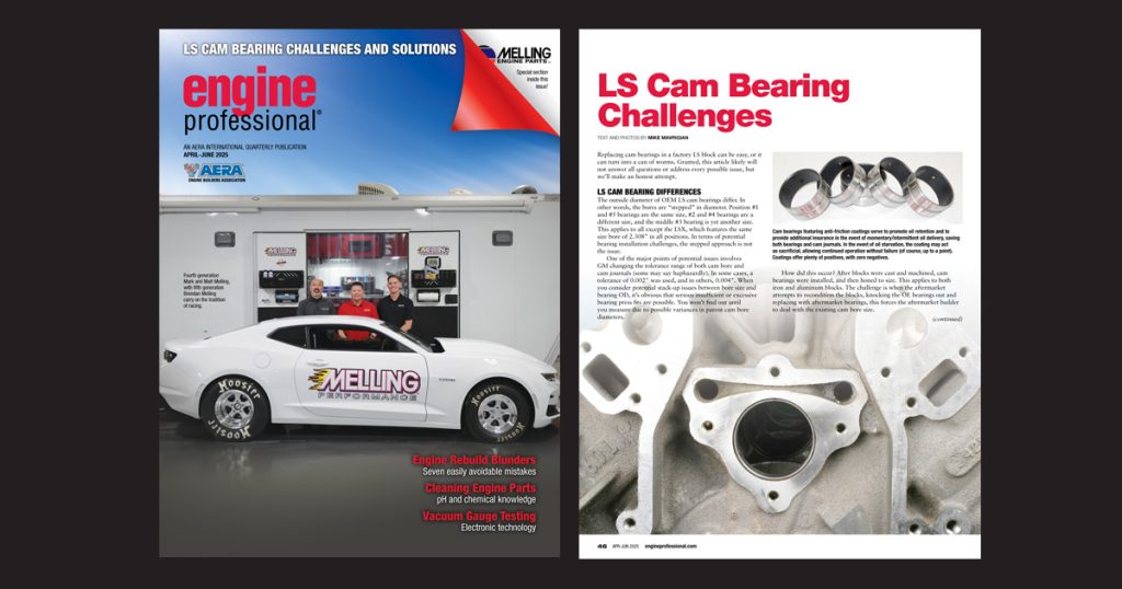
It has been reported that under certain circumstances, the camshaft and bearings may come into contact with each other, resulting in insufficient lubrication. To offer resistance to this situation, which can cause seizure, an alternative coated bearing surface is now available that provides a polymer anti-friction coating.
The use of specialty anti-friction coatings on piston skirts and main & rod bearings is nothing new. It’s been proven that these coatings provide a reduction of friction and a layer of surface protection. Whenever possible/available, it’s always wise to choose Babbit cam bearings that feature a friction-reducing coating on the bearing I.D. These coatings provide several advantages: they aid in oil retention, provide enhanced lubricity, reduce frictional wear and serve as a sacrificial layer in the event of cold starts, momentary oil starvation and can even serve to save the bearings (for a limited time) in the event of a catastrophic loss of oil delivery. Note that if, during disassembly/inspection, a coated cam bearing that shows evidence of coating wear, this does not indicate that the bearing has been damaged. As long as the lead surface of the bearing is intact, the bearing remains serviceable. Again, in the event of an oil delivery issue, the coating serves as a sacrificial layer in an effort to save the bearing.
Coated cam bearings are readily available from bearing makers such as Dura-Bond, Mahle/Clevite, King, Dart, ACL, Daido and others. Of course, uncoated bearings can also be coated by high performance coating companies such as Polymer Dynamics and Swain Tech Coatings. Since bearings are available already coated, it just makes sense to order coated versions to begin with. Given the relative minimal cost of upgrading to coated bearings, the benefits vastly outweigh the added cost.
Some applications also offer Hsg cam bearings (high load fiber reinforced composite PTFE) that provide self lubricating properties and high static load capacity.
LATE MODEL HEMI
As a sidenote, consider cam bearing applications for mate model Hemi engines. Specifically with the Gen III 5.7L, theoretically with regard to cam bearing oil hole orientation, instead of aligning the bearing oil hole at the 6-o’clock position (aligning bearing hole with bore hole) some builder prefer to align the bearing oil hole at the 3-o’clock position. The bearing OD features an oil groove which allows oil to travel around the bearing OD. Placing the bearing oil hole at 3-o’clock allows the vital oil wedge to occur at the approximately 5-7 o’clock, at the point of highest load as the engine operates. The oil then returns to the cam bore oil hole after passing by the bearing oil hole. It has been reported that this provides added lubrication insurance with high valve spring loads.
CAM BEARING TOOLS
Three types of cam bearing installer tools are currently available: the traditional “bearing knocker” type that features a mandrel bar and varying sizes of expanding collets, requiring a dead-blow hammer to drive the bar. An alternative for LS applications is a similar setup but instead of using an expandable collet, an LS-dedicated billet driver is used. Another type is a threaded bar with dual opposing handles (and appropriate sized drivers) that allows you to draw the bearings in place without the use of a hammer. The third, and most current, is a draw-in tool that utilizes hydraulic power to pull the bearings.
In capable hands, the traditional “bearing knocker” style is a proven tool that has been used for decades and continues to be used. However, since repeated blows with a dead hammer applies a shock force to the bearing, this increases the potential for slight bearing distortion, which may require minor cleanup using a sharp bearing scraper. Using a “draw-in” type (threaded or hydraulic) eliminates impact force against the bearings and allows a more controllable positioning of the bearings, virtually eliminating the chance of bearing distortion and eases the act of aligning oil feed holes with the use of Babbit bearings. Draw-in types of installation tools dramatically reduces installation effort. They simply make things easier. Be aware that the threaded-bar draw-in style features twin opposing handles that require clearance to operate. If the block is on a stand, no problem. If the block is on a bench, the block must be perpendicular to the table edge to allow handle clearance.
While any of the styles mentioned here are applicable to steel-backed Babbit bearings as well as needle roller bearings, a draw-in type provides additional safety, since a steady pressure is applied as opposed to impact forces, greatly reducing the potential for damaging the needle bearing cage lips.
ROLLER CAM BEARINGS
Roller (needle) cam bearings offer an alternative to traditional hammer-in press-fit steel-backed Babbit type bearings, and are preferred by many race engine builders.
Installation of needle roller bearings requires absolute cam bore alignment. Any misalignment can not only make it impossible to install the cam but can result in edge-loading of the needle bearings, creating undue stress, resulting in catastrophic bearing failure. Needle roller bearings allow no compensation for alignment issues. Installation alignment must be spot-on.
Extra care must be taken when installing cam roller bearings. Unlike cast bearings that may display a minor burr that can be removed with a sharp bearing scraper, roller bearings offer no such leeway. While roller bearings may be installed using a traditional tool when exercising extreme attention to detail using gentle taps (some employ a rubber “grommet” at the face of the bearing cage), a preferred method that is extremely safe involves a tool that allows you to draw each bearing into place, as opposed to a bar that hammers bearings into their bores. This reduces the chance of distortion of the roller bearing cage. While traditional hammer-bar installation involves pushing each cam bearing into place (pushing the bearings away from the installer). The draw-in type involves pulling the bearings, with the bearing entering its bore from the opposite side of each bore (whether standing at the front or rear of the block), pulling the bearing towards the operator. A precision aluminum cone provides precise bar alignment.
Traditionally, cam bearings are interference-fit cast multi-layer Babbit style bearings. However, many competition engines will feature needle bearings. The advantages of moving to needle bearings in the cam bores include less friction at the cam journals, and a more precise maintaining of the camshaft centerline during engine operation.
A conventional Babbit cam bearing features an oil hole, allowing oil to lubricate the cam journal. The oil clearance between the cam journal and the bearing is filled with oil, so that during camshaft rotation, the cam journals ride on a wedge film of oil (just like rod and main bearings).
A camshaft needle roller bearing allows the cam to ride directly on the bearings. Oil splash is sufficient for lubrication, and the needle bearing housing block off the cam tunnel oil passages, so there is a slight reduction of oil temperature.
In order to install camshaft bore needle bearings, the cam bore must be increased in diameter to achieve proper interference fit for the bearings. This must be done on an alignment boring fixture (or in a CNC machine), and all bores must be machined to the same size (eliminating the stepped approach). In an iron block, the bearing cage should have between 0.0005″ to 0.001″ press fit to the cam bore. If you’re installing the roller bearing in an aluminum block, the bearing cage should have between 0.001″ to 0.0015″ press fit to the cam bore. Excessive press fit can distort and ruin a roller bearing.
For proper installation, a preferred option involves using a thermal technique as opposed to pressing the bearings into place under ambient temperature. This involves freezing the bearing and heating the block for safe installation to avoid bearing cage damage. This allows an easy slip-in installation if you’re concerned about distorting the bearing by hammering or draw-in.
The use of needle bearings requires the use of a camshaft with larger-diameter journals (larger diameter core). This results in a beefier cam core that is less prone to flexing, which is great when using ultra-high-pressure valve springs. Common cam journal diameters, depending on block application, are 50, 55 or 60 mm. Increasing cam journal and bearing size serves to enhance operation and durability in applications where high valve spring pressures are involved. The increase in journal footprint serves to better resist camshaft flex.
The downside to needle bearings: the labor/machining cost to modify a block to accept needle roller bearings is roughly $700 or more (aftermarket race blocks are available already machined for needle bearings). A potential glitch is that the use of needle bearings may promote valvetrain harmonics as opposed to the use of cast Babbit cam bearings, where the cam journals ride on an oil film, which helps to reduce harmonics.
If you want the ultimate and don’t mind paying the price, needle cam bearings are the way to go for certain race applications. Of course, this approach, as with many innovative designs, may be up for argument, with some builders preferring cast or needle bearing designs. If you’re simply building a strong street engine where continuous high engine speed isn’t a factor, it’s a waste of money and is not recommended. Since needle roller bearings rely on oil splash (plenty available in hi-rev engines), street operation may or may not provide adequate oil.
In some aftermarket aluminum race blocks, the block is designed up-front for the use of roller cam bearings. Some blocks use special “stopper” bolts which are installed from the lifter valley, one on each side (fore/aft) of the cam bearing location. This prevents the cam bearing from walking/moving fore or aft during engine operation, eliminating reliance of the press fit alone.
CHECK FOR RUNOUT
All camshafts, whether new or used, should be checked for runout prior to installation, simply to confirm that the cam is straight. A cam with excessive runout will result in cam bearing clearance issues and bearing damage, in addition to erratic valve opening and closing rates and erratic timing. Alignment is even more critical when using roller bearings. Rest the cam on clean V-blocks and set up a dial indicator at the cam’s center journal. After pre-loading the dial indicator plunger by about 0.050-inch, adjust the gauge to zero. Rotate the cam slowly and observe for runout. Ideally there should be zero runout, with a bit less than about 0.001-inch runout considered allowable. Any more than that indicates the cam is bent or the center journal was ground out of round and the cam should be replaced.
CAM BEARING SERVICE TOOL EXAMPLES
- BHJ Products (draw-in tool CBT-1) 510-797-6780 / bhjproducts.com
- Bonefied Tools (hydraulic draw-in tool) 616-856-1062 / bonefiedtools@gmail.com
- Comp Cams (array of traditional draw-bar tool sets and tool 5412 that draws bearings into position) 800-999-0853 / compcams.com
- Goodson Tools & Supplies (universal cam bearing installer CBT-300)
800-533-8010 / goodson.com - Powerhouse Products (draw-in tool 5412) 800-365-9145 / powerhouseproducts.com
CAM BEARING SOURCES
A wide selection of cast bearings are available from numerous sources, while roller bearings are available from a limited number of makers. Following are examples.
- ACL: 800-847-5521 / aclraceseries.com
- Daido Metal: 217-259-7827/ daidometal.com
- Dura-Bond (cast bearings): 775-883-8998 / dura-bondbearing.com
- Comp Cams (cast and roller bearings): 800-999-0853 / compcams.com
- Dart Machinery (cast bearings and roller bearings): 248-362-1188 / dartheads.com
- MAHLE/Clevite (cast bearings): 662-892-6400 / mahle-aftermarket.com
- INA / Schaeffler Group USA (roller cam bearings): 803-548-8981
- Jesel Valvetrain (cast and roller bearings): 732-901-1800 / tech@jesel.com
- King Engine Bearings (cast bearings): 973-857-0705 / kingbearings.com
- Sealed Power (cast bearings): 800-325-8886 / drivparts.com
Read this article with all images in the digital issue of Engine Professional magazine https://engineprofessional.com/2025EPQ2/#p=48