By Andy Kennedy
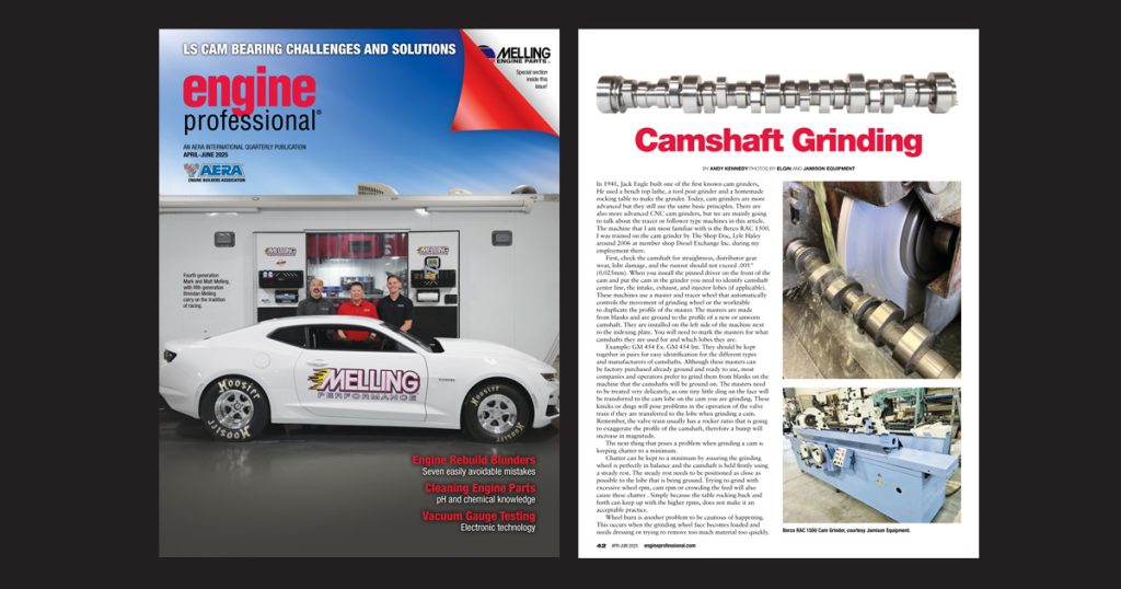
In 1941, Jack Engle built one of the first known cam grinders. He used a bench top lathe, a tool post grinder and a homemade rocking table to make the grinder. Today, cam grinders are more advanced but they still use the same basic principles. There are also more advanced CNC cam grinders, but we are mainly going to talk about the tracer or follower type machines in this article. The machine that I am most familiar with is the Berco RAC 1500. I was trained on the cam grinder by The Shop Doc, Lyle Haley around 2006 at member shop Diesel Exchange Inc. during my employment there.
First, check the camshaft for straightness, distributor gear wear, lobe damage, and the runout should not exceed .001″ (0.025mm). When you install the pinned driver on the front of the cam and put the cam in the grinder you need to identify camshaft center line, the intake, exhaust, and injector lobes (if applicable). These machines use a master and tracer wheel that automatically controls the movement of grinding wheel or the worktable to duplicate the profile of the master. The masters are made from blanks and are ground to the profile of a new or unworn camshaft. They are installed on the left side of the machine next to the indexing plate. You will need to mark the masters for what camshafts they are used for and which lobes they are.
Read this article with all images in the digital issue of Engine Professional magazine https://engineprofessional.com/2025EPQ2/#p=44
Example: GM 454 Ex. GM 454 Int. They should be kept together in pairs for easy identification for the different types and manufacturers of camshafts. Although these masters can be factory purchased already ground and ready to use, most companies and operators prefer to grind them from blanks on the machine that the camshafts will be ground on. The masters need to be treated very delicately, as one tiny little ding on the face will be transferred to the cam lobe on the cam you are grinding. These knicks or dings will pose problems in the operation of the valve train if they are transferred to the lobe when grinding a cam. Remember, the valve train usually has a rocker ratio that is going to exaggerate the profile of the camshaft, therefore a bump will increase in magnitude.
The next thing that poses a problem when grinding a cam is keeping chatter to a minimum.
Chatter can be kept to a minimum by assuring the grinding wheel is perfectly in balance and the camshaft is held firmly using a steady rest. The steady rest needs to be positioned as close as possible to the lobe that is being ground. Trying to grind with excessive wheel rpm, cam rpm or crowding the feed will also cause these chatter . Simply because the table rocking back and forth can keep up with the higher rpms, does not make it an acceptable practice.
Wheel burn is another problem to be cautious of happening. This occurs when the grinding wheel face becomes loaded and needs dressing or trying to remove too much material too quickly. Always allow the wheel to spark out before backing the wheel off the lobe, as this can result in high spots/lift off bumps on the lobe that will be magnified by rocker ratio.
A lot of people ask, “How can you grind a cam, remove material, and increase the lobe lift and cam duration by doing so?” The answer to that is most of the material is removed from the base circle of the cam and not from the nose. When you are going to change the lobes profile from what it was originally, it can dramatically affect the engine performance and characteristics of the camshaft.
As cam grinding has been around for many years, a lot of shops do not find it feasible to make commitment to grinding cams, simply because it is a significant cost and many cams (especially automotive) it’s cheaper to just purchase them new. In a diesel shop, it can be a very cost-effective alternative to purchasing new cams.
Read this article with all images in the digital issue of Engine Professional magazine https://engineprofessional.com/2025EPQ2/#p=44