By Mike Mavrigian
For engines designed to produce high levels of both horsepower and torque, only high quality aftermarket forged steel, aluminum or titanium rods should be considered.
Connecting rods provide the critical connection between the crankshaft and the pistons. Rods must be capable of withstanding enormous compression force and the transitional dynamics that take place during the approach to top dead center and being forced back down after TDC. Rods are subjected to incredible compression and stretch forces, making tensile strength, rigidity and weight primary considerations.
Read this article with all images in the digital issue of Engine Professional magazine https://engineprofessional.com/2025EPQ4/#p=36
TYPES OF RODS
In this article we will ignore old-school cast OEM rods, focusing instead on performance materials and designs available in the aftermarket. Material and manufacturing formats here will include forged steel, forged aluminum, billet and titanium.
Regardless of material or design, today’s performance aftermarket rod makers employ superior materials for strength and durability, high-precision CNC machining and typically offer tight-tolerance/more uniform weight, minimizing the need for modifications in order to achieve consistent small end and big end balancing. Also, to accommodate stroker builds, many performance rods tend to feature reduced big end shoulder profiles to aid in minimizing the need for block reliefs.
BEAM DESIGN
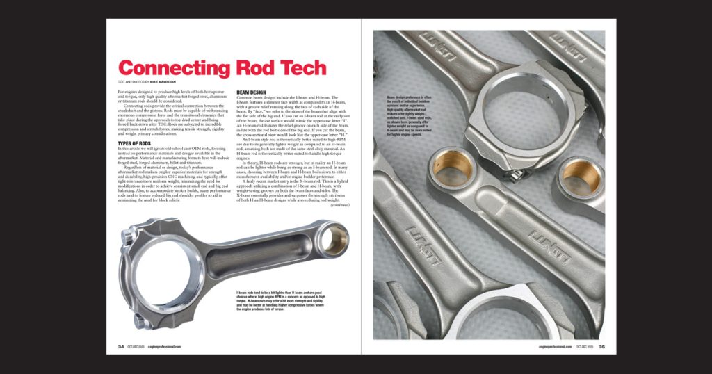
Common beam designs include the I-beam and H-beam. The I-beam features a slimmer face width as compared to an H-beam, with a groove relief running along the face of each side of the beam. By “face,” we refer to the sides of the beam that align with the flat side of the big end. If you cut an I-beam rod at the midpoint of the beam, the cut surface would mimic the upper-case letter “I”. An H-beam rod features the relief groove on each side of the beam, in-line with the rod bolt sides of the big end. If you cut the beam, the cross-sectional view would look like the upper-case letter “H.”
An I-beam style rod is theoretically better suited to high-RPM use due to its generally lighter weight as compared to an H-beam rod, assuming both are made of the same steel alloy material. An H-beam rod is theoretically better suited to handle high-torque engines.
In theory, H-beam rods are stronger, but in reality an H-beam rod can be lighter while being as strong as an I-beam rod. In many cases, choosing between I-beam and H-beam boils down to either manufacturer availability and/or engine builder preference.
A fairly recent market entry is the X-beam rod. This is a hybrid approach utilizing a combination of I-beam and H-beam, with weight-saving grooves on both the beam faces and sides. The X-beam essentially provides and surpasses the strength attributes of both H and I-beam designs while also reducing rod weight. The X-beam design was developed to provide additional tensile strength and to better handle extreme compressive forces for high HP applications for supercharged and turbocharged high-boost engines where extreme horsepower and high engine rpm is anticipated. This is sometimes available on bulky aluminum rods to provide both a level of weight reduction and an increase of surface area for enhanced strength.
Today’s performance connecting rods (offered by leading makers) are often weight matched to within +/- 1 gram, virtually eliminating the need to remove additional weight during the balancing procedure.
FORGED STEEL RODS
Ford steel connecting rods are made by heating a dense slug of alloy steel. This commonly features 4340 steel, heated to a malleable state at about 2200°F. This is followed by pressure forming under as much as 240,000 pounds of pressure in a forging die. The forging process results in an extremely strong unit with a tight molecular grain, followed by heat treating and stress relieving. This makes the metal stronger, with a tighter, more-compacted and uniform metallurgical grain structure. The raw forging may then be induction hardened, shot-peened and/ or cryogenically stress-relieved and heat treated.
The forging is heat treated prior to final machining, since the heat treating/tempering process can deform the part’s shape by as much as 0.060″. The rod is then CNC machined, the raw cap is cut away, and both mating surfaces are machined to create a light undersize The cap is then installed and the big end is machined to create a perfectly round hole, at a precise diameter. Once machining is complete, the rod is stress relieved and surface hardened.
ALUMINUM ALLOY RODS
Aluminum rods may be lighter as compared to forged steel, but they’re more expensive, and they’re bulkier, resulting in increased clearance concerns relative to the block. Aluminum rods begin life as dense forgings or dense-forged billet stock that are CNC machined to final shape. The materials commonly feature 7075 or 7075-T6 aluminum alloy. Die-forging provides a more highly-dense grain structure for added strength. During the forging process, the material is exposed to about 700°F, and impacted with as much as 2200 tons of pressure, resulting in enhanced grain flow and material density.
As already noted, while weight reduction is a plus, due to the increased thickness, more attention is required in terms of clearance checking. If aluminum rods are used, just as hard washers are needed for aluminum cylinder head bolt locations, hardened washers must be installed under the rod bolt heads to prevent the bolt heads from digging into the parent aluminum. Aluminum rods are popular for extremely high RPM and are commonly used for high-level drag racing applications, as the aluminum flexes and serves to absorb compressive and transitional to/from TDC. However, that characteristic makes them unsuitable for road race applications where the flexing under loads are continuous. A common misconception is that aluminum rods stretch too much. Yes, the material expands more as compared to steel, but in terms of overall length growth, the rod may only grow under operating temperature by only a few thousandths of an inch. Obviously, piston to valve clearance must be more tightly adhered to. Aluminum rods typically feature an I-beam design for clearance reasons. Since an aluminum rod beam must be wider to begin with, an H-beam design would make the beams even wider. One downside to aluminum rods, aside from the higher price, is cycle life. Because the material grows and flexes, the fatigue life is shorter as compared to steel, so the frequency need to replace them in terms of number of races/runs is greater.
BILLET RODS
Billet rods begin life as a dense-grain forged plate stock, then CNC machined to shape. Billet rods are available in either steel or aluminum alloys. The cost of billet rods is higher in comparison, simply due to the material wasted during machining from a forged blank and the increased labor/machine time involved. Billet rods also offer another advantage: since the rod is to be machined from a blank, this allows you to obtain custom rod dimensions, for those who are developing their own platforms and feel the need to experiment with specific length, width and beam shapes, for those rare instances where available in-stock rods aren’t available to meet custom requirements.
TITANIUM RODS
The claim to fame of titanium focuses on its reduced weight as compared to a steel or aluminum rod of the same size, and it’s strength-to-weight ratio. Typically, a titanium rod is machined from Ti6AL4V stock, which is about approximately 33% lighter than a comparable-sized forged steel rod. This obviously reduces the reciprocating weight, an advantage in terms of more quickly achieving engine speeds.
The disadvantages of titanium are higher cost and the need for increased care and attention in terms of nicks or scratches. While the lightweight alloy may offer high tensile strength, titanium can be very susceptible to failure from stress risers. Also, when exposed to contact friction (for example, if big ends make contact with each other on a common journal) the material may have a tendency to gall. To reduce this concern, titanium rods big end sides may be either highly polished or treated to a hard-surface coating.
DIMENSION EXPLANATION
Block Deck Height: distance from the centerline of the main bore to the deck surface.
Crank stroke factor: We consider only half of total crank stroke, from crank main centerline to rod journal centerline when the rod journal is at TDC.
Rod Length: The distance from the centerline of the big end bore to the centerline of the small end/wrist pin bore.
Piston CD: The “compression distance” from the centerline of the wrist pin bore to the piston dome at the dome’s flat area that meets the block deck.
Example: using a block that we have surfaced to a deck height of 9.000-inch, and a crankshaft that features a 4.125-inch total stroke, we can easily determine required rod length and piston CD.
Since our goal in this example may be to achieve a zero-deck piston to deck clearance, we know that our total crank/rod/piston combo needs to be 9.000-inch.
Since we’re using a 4.000-inch stroke crank, and we’re only going to factor one half of total stroke, we can immediately subtract 2.000-inch from our 9.000-inch goal, leaving 7.000-inches to be made up with our rod and piston.
Now say that we wish to use a 6.000-inch rod. Subtracting that from our previous 7.000-inch subtotal, that means that we need a piston that has a 1.000-inch CD.
If we opted to use a stroke of 3.875-inch, coupled with a 6.000-inch rod, using the same formula, our piston would require a CD of 1.062-inch.
CONNECTING ROD RATIO
This refers to the combination of crankshaft stroke and connecting rod length. Changes in rod ratio affect the operating angle of the rods, which in turn affect piston thrust load and friction between piston skirts and the cylinder walls.
Rod ratio is calculated by dividing rod length by crank stroke. For example, if the crankshaft features a stroke of 4.000-inch and the rod length is 6.000-inch, 6.000 divided by 4.000 = 1.5:1 rod ratio. By increasing stroke or by using a shorter rod, rod ratio decreases. If stroke is reduced or a longer rod is used, rod ratio increases. Generally speaking, for street and high performance use, rod ratios in the 1.5 – 1.8 range are acceptable, with about 1.75:1 considered by some as “ideal.” However, extreme performance applications sometimes use ratios as high as 1.9 – 2:1.
As an example, let’s compare 5.700-inch rods to 6.000-inch rods, keeping crank stroke unchanged. A shorter rod causes the piston to spend a bit less time dwelling at top-dead-center (TDC). A longer rod causes the piston to dwell longer at TDC, resulting in greater combustion pressure. A 5.700-inch rod allows the piston to dwell for about 2-3 degrees at TDC, while a 6.000-inch rod allows the piston to dwell at TDC about 9-10 degrees, The longer dwell time with a longer rod helps to flatten out the torque curve an allows you to use higher compression ratio on pump gas. A longer rod aids the engine to pull better in high a high RPM range.
The use of a longer rod also allows the use of pistons with a shorter compression distance (distance from the wrist pin centerline to the dome), which allows for a shorter skirt length, reducing weight mass. In basic terms, a longer rod provides more torque at high RPMs, and reduces friction due to the reduced operational angle as compared to a shorter rod.
When determining rod length that “fits” your build, you must consider these factors:
• Block deck height
• ½ Crank stroke
• Piston compression height
One-half of the crankshaft stroke is factored when determining rod length because the location of the crank rod journal at TDC influences the placement of the piston dome relative to the block deck. If the crank features a 4.000-inch stroke, we only factor in one half of the total stroke, which in this case is 2.000-inch. The half-stroke dimension, coupled with rod length and piston compression height combines to place the piston dome at the block deck, whether this is desired at zero, or slightly below deck, according to the builder’s plan.
While rod ratio is certainly a factor to consider, other factors such as displacement, compression ratio, cylinder head flow, cam timing and exhaust scavenging play a bigger role.
ROD TO BLOCK CLEARANCE
A test mockup is essential with regard to checking rod-to-block clearance, especially when stroke is increased. As stroke is increased, the rod big ends move closer to the block, below cylinders and at the oil pan rails. With the crank installed on its bearings, mock-install the piston/rod, with rod bearings in place. There’s no need to fully torque the rod bolts at this point. Just snug to make the cap flush to the rod saddle and slowly rotate the crank, observing clearances. If clearance is too tight, mark the block interference locations with a marker. Do this with each rod location. With all components removed and you’re back to a bare block, carefully grind material to obtain clearance. Clean the block and repeat the test assembly, again verifying clearances. As a general rule, you want at least 0.080-inch clearance at all rod-to-block locations.
In addition to potential rod big end to block concerns, rod to the camshaft clearance concerns may also arise when stroke is increased, when using big, fat aluminum rods, and/or when a camshaft features a larger base circle. This is why aftermarket blocks are available with raised cam tunnels, to move the cam away from possible rod strikes.
ROD SIDE CLEARANCE
Rod side clearance is important. Too tight and the pair of rods on a common journal will rub against each other, creating friction, potential galling and excess heat being transferred to rod bearings. Too loose and the rods can slide excessively fore/aft, which can place undue loads on the rod bearings and at the piston pin area, which can adversely affect piston skirt side loading at the cylinder walls.
During test fitting, spread the pair of rods on a common journal and place a clean feeler gauge between the rod sides. A generally recommended clearance is in the range of 0.012-inch to a maximum of about 0.019-0.020-inch.
ROD BOLT TIPS
The fit and tensile strength of the rod bolts is absolutely critical, especially for high performance applications. While it was standard practice to upgrade OEM rods with high quality rod bolts such as those offered by ARP as an example, today’s aftermarket performance rods are always assembled and shipped with high-quality/high-strength rod bolts. These high performance rod bots typically feature a 12-point head design. The 12-point design provides a more secure engagement, naturally driven by a 12-point wrench, but this design also allows the use of a smaller-diameter head, which provides easier access due to the smaller outer diameter of the appropriate-sized socket wrench.
High performance rod bolts designed for racing applications are also available in a variety of thread diameters. Shank lengths and material formulation, all of which affect the recommended installation torque and maximum allowable bolt stretch.
A numeric “code” is commonly featured on the bolt head that indicates the type of material. Again, citing ARP as an example, typical materials are 8740 or 2000. 8740 rod bolts are chromoly offering tensile strength of 180,000 to 210,000 psi, adequate for most racing applications, 2000 rod bolts differ in alloy formulation and can provide higher clamping loads of as much as 220,000 psi. A set of aftermarket rods will include a spec sheet that provides the recommended torque value and the “not to exceed” amount of bolt stretch, based on thread diameter, shank length and type of material. For example, a set of connecting rods equipped with ARP rod bolts includes a spec sheet that lists torque and max stretch for 5/16 x 1.500-inch ARP 2000, 3/8 x 1.600-inch ARP 8740, 3/8 x 1.600-inch ARP 2000, 7/16 x 1.400-inch ARP 8740, 7/16 x 1.500-inch SCAT 2001, 7/16 x 1.600-inch ARP 8740, 7/16 x 1.600-inch ARP 2000, 7/16 x 1.800-inch ARP 8740 and 7/16 x 1.800-inch SCAT 2001 cap screws, each with its own recommended torque value and amount of bolt stretch that is not to be exceeded.
Because of the popular method of rod bolt installation involves monitoring installed bolt stretch/degree of elasticity, performance rod bolts will typically feature a dimple at each end, to provide engagement points for the use of a rod bolt stretch gauge.
TIGHTENING ROD BOLTS BY MONITORING STRETCH
While I dislike referring to “the old days,” when it comes to addressing the topic of tightening connecting rod bolts, rather than applying a specified torque value alone, the use of monitoring the amount of bolt stretch provides distinct advantages of not only achieving a more accurate degree of clamping force, but as a way to monitor and maintain records of each bolt’s condition. A bolt, such as used in a high tensile application such as connecting rod applications, can be viewed as an “elastic” component. When exposed to a specific amount of clamping force, the bolt slightly stretches, or elongates, displaying a degree of “rubber band” elasticity. If under-tightened, insufficient clamping force between the rod saddle and cap won’t be achieved, potentially allowing the cap to slightly pull away from the saddle, reducing rod bearing crush. If over-tightened, the bolt may be pulled beyond is elastic state where the “rubber band” effect is lost, in which case the bolt becomes weakened with resulting bearing looseness and potential rod bolt failure.
As noted, checking and monitoring rod bolt stretch provides a more accurate achievement of clamping force, because this eliminates the potential frictional factor that is experienced when relying on applied torque value alone. By staying within the specified stretch, we are measuring and recording the actual elastic range of the bolt. This is extremely useful when engines are repeatedly rebuilt and/or inspected between races. By recording each individual rod bolt’s location in terms of initially installed stretch, we can re-check to see how far the bolt stretches under a given torque value. For example, if a bolt initially stretched by 0.0045-inch when torqued to 70 ft-lb, but now that same bolt stretches 0.006-inch at the same torque value, we can determine that the bolt is no longer within spec and must be replaced.
Rod bolt stretch gauges are offered by several sources such as ARP, Goodson Tools, Moroso and others. The gauge features a dial indicator, a fixed pointed anvil and an opposing spring-loaded adjustable centering probe. The pointed ends engage to the rod bolt at the bolt’s head and shank tip dimples. Prior to installing the rod bolt, place it in the gauge, applying a small preload. Adjust the gauge to read zero. This provides a static free-length of the bolt.
Remove the bolt from the gauge, lube and install to the rod. Do not change the current needle setting on the dial indicator. If the specified torque value for that application calls for 70 ft-lb, using a torque wrench, tighten to 70 ft-lb. Then install the stretch gauge. Since you zeroed the gauge at the bolt’s free length, the gauge will now show how far the bolt has stretched at your torque value. For example, if the rod maker’s spec sheet lists a stretch not to exceed 0.0062-inch, and your stretch reading shows 0.006-inch, you know that you are within the allowable range. You may prefer to begin by torqueing the bolt to 50 ft-lb, then 60 ft-lb, etc., checking stretch after each torque application, to provide a picture of how mush stretch is occurring as you increase applied torque.
Note that the stretch gauge must be individually zero’d for each bolt, as individual bolt lengths and dimple depths can vary. In other words, do not assume that by zeroing the gauge for one bolt, that the remaining bolts will zero at the same point n the gauge. Treat each bolt as a unique part.
REM FINISHING
REM finishing has become increasingly popular for applications including crankshafts, connecting rods, camshafts, and more. This is essentially a chemical and tumble-polishing process that smooths-out the surface finish to an almost chrome-plated appearance. The advantages include micro polishing to reduce or eliminate microscopic machining peaks and valleys, resulting in a more uniform and uninterrupted surface, and softens any sharp edges, which eliminates potential stress risers. The ultra-slick finish also helps to shed parasitic oil cling, potentially freeing-up power due to reduced drag. REM finishing services are available from some rod makers as an option, as well as independent metal finishing services across the country. Costs vary, but typically this process for a crank and a full set of rods may run in the range of $500-$600.
Read this article with all images in the digital issue of Engine Professional magazine https://engineprofessional.com/2025EPQ4/#p=36