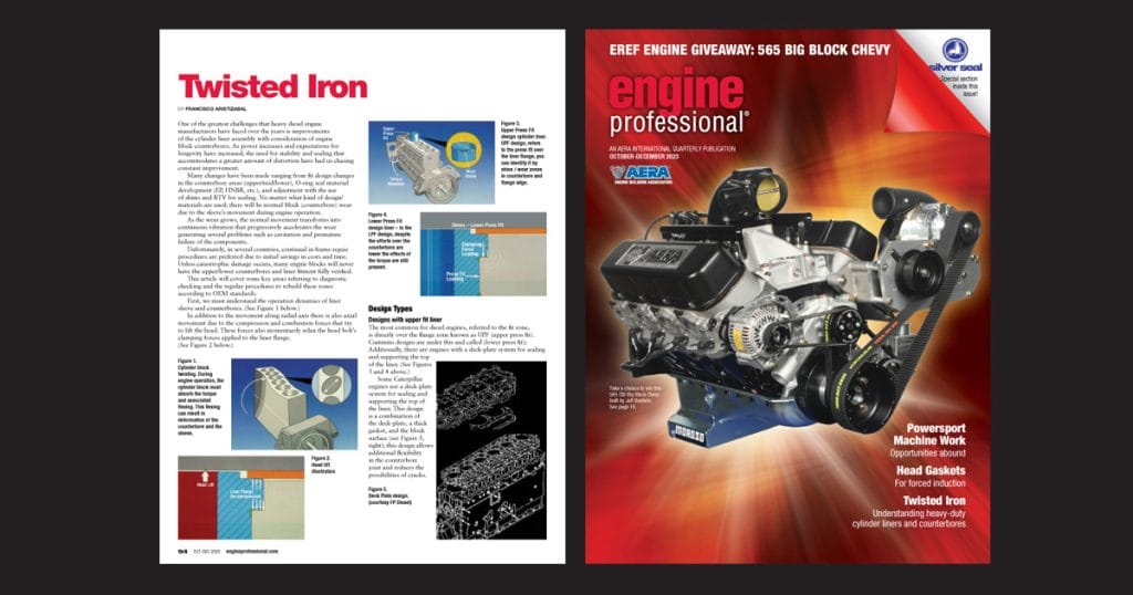
By Francisco Aristizabal
One of the greatest challenges that heavy diesel engine manufacturers have faced over the years is improvements of the cylinder liner assembly with consideration of engine block counterbores. As power increases and expectations for longevity have increased, the need for stability and sealing that accommodates a greater amount of distortion have had us chasing constant improvement.
Many changes have been made ranging from fit design changes in the counterbore areas (upper/mid/lower), O-ring seal material development (EP, HNBR, etc.), and adjustment with the use of shims and RTV for sealing. No matter what kind of design/materials are used; there will be normal block (counterbore) wear due to the sleeve’s movement during engine operation.
As the wear grows, the normal movement transforms into continuous vibration that progressively accelerates the wear generating several problems such as cavitation and premature failure of the components.
Unfortunately, in several countries, continual in-frame repair procedures are preferred due to initial savings in costs and time. Unless catastrophic damage occurs, many engine blocks will never have the upper/lower counterbores and liner fitment fully verified.
This article will cover some key areas referring to diagnostic checking and the regular procedures to rebuild these zones according to OEM standards.
First, we must understand the operation dynamics of liner sleeve and counterbores. (See Figure 1.)
To view this article with all images in the digital version of Engine Professional magazine, go to https://engineprofessional.com/2023EPQ4/#p=96
In addition to the movement along radial axis there is also axial movement due to the compression and combustion forces that try to lift the head. These forces also momentarily relax the head bolt’s clamping forces applied to the liner flange. (See Figure 2.)
Design Types
Designs with upper fit liner: The most common for diesel engines, referred to the fit zone, is directly over the flange zone known as UPF (upper press fit). Cummins designs are under this and called (lower press fit); Additionally, there are engines with a deck-plate system for sealing and supporting the top of the liner. (See Figures 3 and 4.)
Some Caterpillar engines use a deck-plate system for sealing and supporting the top of the liner. This design is a combination of the deck-plate, a thick gasket, and the block surface (see Figure 5); this design allows additional flexibility in the counterbore joint and reduces the possibilities of cracks.
Mid liner fit designs: Most recently engines have a mid-stop design liner; these liners have a similar “flange zone” at or near the middle of the liner, the counterbore in the block is in the middle as well (see Figure 6).
Although, no matter the design, the torque and decompression forces always have been present and a relative movement exists, with unavoidable block wear.
Counterbore Measuring
The measuring process seeks to determine if counterbores (upper and lower) are within OEM specifications. Nevertheless, the specific recommendations of each manufacturer, as a general rule, are no differences greater than 0.001″ between the four measuring points (90° each, see Figure 7). More than that will require machine work and the subsequent use of shims to properly set up the liner height protrusion (if necessary).
If counterbore diameters exceed the maximum OEM allowed value, a machining process must be performed to use an oversized flanged liner (if available) or to install counterbore repair sleeves to assure the required fit.
The lower block counterbore is another story; Things to lookout for are radial clearance that is commonly between 0.002” and 0.008” related to the liner, a smooth surface that has no damage to the O-ring seals, and proper liner installation is mandatory; Unfortunately, this zone is mainly affected by corrosion and hardened deposits.
There are not a lot of options that exist beyond machining to install lower block counterbore inserts; OEMs and aftermarket brands offer different option sizes for these and the upper block inserts.
Counterbore Machining
Be careful cutting the counterbore including ledge and chamfer (see Figure 8). Use OEM recommendations to allow for the correct liner joint and help avoid flange breakage, the cutting speed and tool bit radius are issues to be considered carefully.
Counterbore Repair Sleeves
To install the sleeve, the block must be clean and dry; the sleeve must be frozen and high strength anerobic sealant/retainer is recommended. Be careful to get it in the right position when installing (ID tapered or not), use the recommended tool to get it seated into place (see Figure 9), allow appropriate time for adhesive drying action before final machining (see Figure 10).
As you can see, understanding the different joints liner/block can help you approach these kind of repairs. Currently other methods are used to rebuild these areas like the metallization processes, which also means that there are plenty of opportunities for the engine machinist industry to do these repairs. As AERA’s new tech specialist, hopefully this is good information members will benefit from. You can contact us in the Technical Department at 888-324-2372 or email tech@aera.org for the specifications required for these repairs.
To view this article with all images in the digital version of Engine Professional magazine, go to https://engineprofessional.com/2023EPQ4/#p=96

