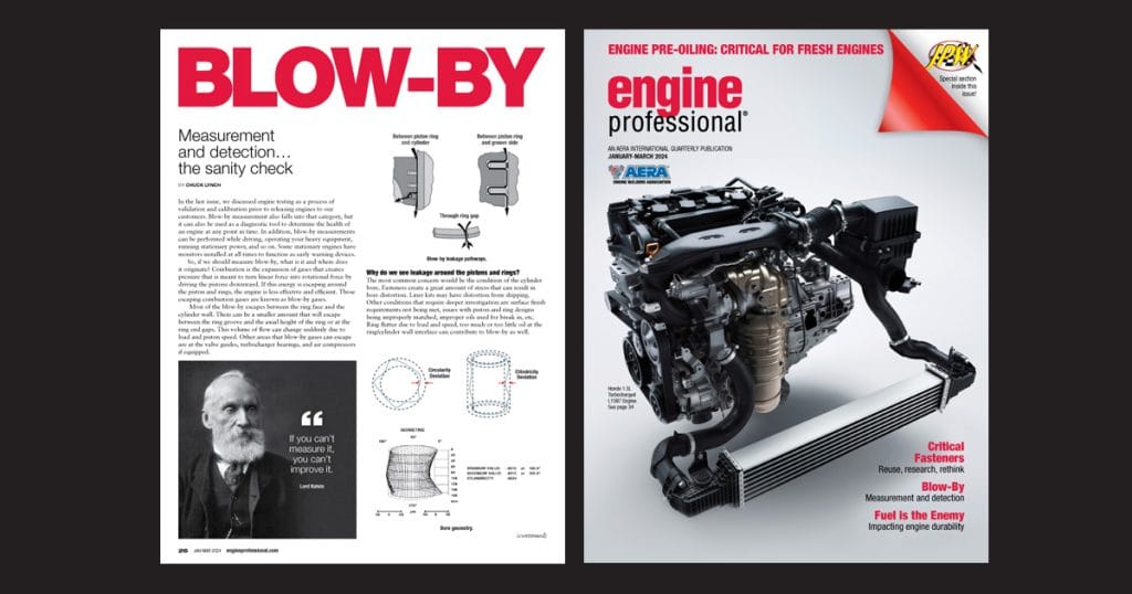
The sanity check
By Chuck Lynch
In the last issue, we discussed engine testing as a process of validation and calibration prior to releasing engines to our customers. Blow-by measurement also falls into that category, but it can also be used as a diagnostic tool to determine the health of an engine at any point in time. In addition, blow-by measurements can be performed while driving, operating your heavy equipment, running stationary power, and so on. Some stationary engines have monitors installed at all times to function as early warning devices.
So, if we should measure blow-by, what is it and where does it originate? Combustion is the expansion of gases that creates pressure that is meant to turn linear force into rotational force by driving the pistons downward. If this energy is escaping around the piston and rings, the engine is less effective and efficient. Those escaping combustion gases are known as blow-by gases.
Read this article with all images in the digital issue of Engine Professional magazine https://engineprofessional.com/2024EPQ1/#p=28
Most of the blow-by escapes between the ring face and the cylinder wall. There can be a smaller amount that will escape between the ring groove and the axial height of the ring or at the ring end gaps. This volume of flow can change suddenly due to load and piston speed. Other areas that blow-by gases can escape are at the valve guides, turbocharger bearings, and air compressors if equipped.
Why do we see leakage around the pistons and rings?
The most common concern would be the condition of the cylinder bore. Fasteners create a great amount of stress that can result in bore distortion. Liner kits may have distortion from shipping. Other conditions that require deeper investigation are surface finish requirements not being met, issues with piston and ring designs being improperly matched, improper oils used for break in, etc. Ring flutter due to load and speed, too much or too little oil at the ring/cylinder wall interface can contribute to blow-by as well.
As mentioned earlier, blow-by can escape around turbocharger bearings. On the inverse, turbocharger boost can escape into the crankcase if the turbocharger scarf cut shaft seals are cut at the wrong angle, the gaps are loose, or the seal to groove dimensions are otherwise incorrect. This is often mistaken as piston and ring induced blow-by and the typical correction methods do not fix the issue. This can be determined by isolating the turbocharger from the crankcase by removing the turbocharger oil drain and running it to a catch can and again assessing the blow-by volume. If the blow-by volume is significantly lower, there is an issue with the turbocharger.
What methods can be used to measure blow-by?
We know that technicians may look for fogging or mist coming from breathers, crankshaft seal failures or they may complain of low power, oil consumption, and blame these on blow-by. Although these symptoms may in fact be due to blow-by, it does not put a quantifiable number to the severity of the condition, and you may perform a lot of work that is not related to root cause. Remember, at the core of the issue is leakage at the piston, rings, and cylinder wall. That fact means that the repair is a significant amount of work and can be quite costly in terms of both time and materials. Therefore, you should ideally use a manometer or blow-by meter.
What is a manometer?
Manometers can be analog or digital. The U-tube manometer (commonly used in engine testing), is a U-shaped glass tube partially filled with liquid. This manometer has no moving parts and requires no calibration. Manometry measurements are functions of gravity and the liquid’s density, both physical properties that make the U-tube manometer a NIST standard for accuracy. The manometer is connected to the engine breather system and mounted somewhere that it can be observed. This is challenging to accurately monitor but has been used for many years and several diesel engine service manuals have parameters for manometer use.
Blow-by meters give you the ability to capture and record data rather than try to discern whether you caught the movement in the column at the correct time as the engine accelerates and decelerates. There are several principles for blow-by measurement. Vortex, orifice, floater, hot-wire, impeller and gas meter. The vortex is the most widely used in North America.
Vortex Blow-by meter operates on a vortex shedding principle which provides a fast response and an insensitivity to temperature, pressure, and velocity. There are no moving parts in the meter and the vortex shedding principle ensures highly repeatable stability. The measurement principles of these instruments are based on an effect observed by Leonardo da Vinci, stating a body held in a flow causes a vortex (Annual Review of Fluid Mechanics).
We recently had the opportunity to be involved in some significant blow-by testing at Wagler Competition Products as shown in the images at the right. Total Seal and Wagler were testing rings, and it was a great opportunity to get a lot of pulls, thus testing repeatability/reproducibility of the blow-by monitoring system with tuning and data acquisition support from S&S Diesel. AERA member J-TEC Associates produces flow meters for internal combustion engine air-intake, exhaust, and crankcase blow-by flow measurement. You can check this out on the J-TEC YouTube channel or check out their website at j-tecassociates.com.
If you are an engine machinist, engine builder or a technician that performs engine repairs, there are methods to quantify these blow-by complaints that we have all received at some point. One of my favorite quotes is attributed to mathematician Lord Kelvin, “If you can’t measure it, you can’t improve it.” When our troubleshooting strategy is akin to a shotgun blast, we can make a lot of wrong adjustments before we make the correct adjustment. Having the tools that bring more clarity to the issue can save us a lot of time, parts cost, and frustration. Look before you leap.
Read this article with all images in the digital issue of Engine Professional magazine https://engineprofessional.com/2024EPQ1/#p=28