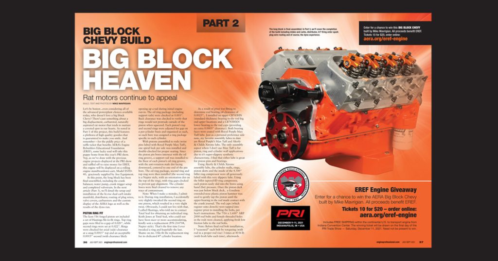
Big Block Heaven
By Mike Mavrigian
NOTE: This article covers our 2021 EREF engine build (part 2 of 3), originally published in our Q3 July-September 2021 issue.
Let’s be honest…even considering all of the advanced powerplant choices available today, who doesn’t love a big block Chevy? There’s just something about a big displacement, carbureted, naturally aspirated rat motor that tends to nurture a coveted spot in our hearts. As noted in Part 1 of this project, this build features a plethora of high quality goodies that is guaranteed to make you smile. And remember – for the piddly price of a raffle ticket that benefits AERA’s Engine Rebuilders Educational Foundation (EREF), some lucky soul will take this puppy home from this year’s PRI show. Yep, as we’ve done with the previous engine projects displayed at the PRI show and raffled off to raise money for EREF, this engine will be displayed on a rolling engine stand/teardown cart, Model ESTD-40, graciously supplied by Axe Equipment.
At this point, the long block has been final-assembled, including the crank balancer, water pump, crank trigger setup and completed valvetrain. In the next article (Part 3), we’ll detail the setup and installation of the hi-rise dual carb intake manifold, distributor, routing of plug wires, valve covers, carburetors and the custom display of the AERA logo as well as the results of the dyno run.
Read this article with all images in the digital issue of Engine Professional magazine https://engineprofessional.com/2021EPQ3/#p=38
PISTON RING FIT
The Icon 516 forged piston set included a set of Hastings file-to-fit rings. Top ring gaps were filed to a gap of 0.020″, while second rings were set at 0.022″. Rings were checked for axial (side) clearance at a snug 0.0015″ top and an acceptable 0.0015″ second (with clearance likely opening up a tad during initial engine run-in. The oil ring package (including support rails) were checked at 0.003″. Back clearance was checked to verify that rings would not protrude outside of the piston when squeezed. Each piston’s top and second rings were adjusted for gap on a per-cylinder basis and organized as such, so each bore was assigned a ring package specific to each cylinder.
With pistons assembled to rods (wrist pins lubed with Royal Purple Max Tuff), one spiral lock per side was installed and double-checked for proper seating. Since the piston pin bores intersect with the oil ring groove, a support rail was installed to the floor of each piston’s oil ring groove, with the anti-rotation male dot facing downward, centered to one end of the pin bore. The oil ring package, second ring and top ring were then installed (the second ring is a Napier style, with an orientation dot on the top of the ring), with ring gaps clocked to prevent gap alignment. The cylinder bores were final cleaned to remove any trace of contaminant.
Note: When I make a mistake, I admit to it. During ring installation, I accidentally very slightly tweaked the second ring on one piston, which resulted in a very slight twist. Obviously, I could not live with that. I called Hastings, who told me to contact Total Seal for obtaining an individual ring. Keith Jones at Total Seal, who could not have been nicer or more accommodating, kindly sent a replacement (P/N 214704, Napier style). That’s the first time I ever tweaked a ring and hopefully the last. Shame on me. I file-fit the replacement ring for its dedicated #7 cylinder location.
As a result of prior test fitting to determine rod bearing oil clearance of 0.0025″, I installed an upper CB743HN (standard thickness) bearing to the rod big end upper locations and a CB743HXN lower bearing to the rod caps (providing an extra 0.0005″ clearance). Both bearing faces were coated with Royal Purple Max Tuff lube. Just as a personal preference side note, my favorite assembly lubes to date are Royal Purple’s Max Tuff and Akerly & Childs Xtreme lube. The only assembly aspect where I don’t use Max Tuff is for piston, ring and cylinder wall applications due to it’s super-slippery synthetic characteristic. I find that either lube is great for piston pins and bearings.
Using Akerly & Childs Xtreme assembly lube, the cylinder walls, rings, piston skirts and the inside of the 4.500″ billet ring compressor were all generously lubed with this very slippery lube. Using the billet tapered-ID ring compressor, each piston easily slid into the bores using hand (fist) pressure. Once the piston deck was just below block deck, a Goodson extended-nose plastic piston hammer was used to gently tap the piston until the upper-bearing in the rod made contact with the crank journal. The rod caps (which register onto dowels) were tapped into register prior to installing the bolts, per Scat’s instructions. The 7/16 x 1.600″ ARP 2000 rod bolts and female threaded holes in the rods were cleaned, applying fresh low friction lube to the rod bolts.
Note: Before final rod bolt installation, I “seasoned” each bolt by torqueing (with rod in a proper rod vise) 3 times at 40 ft-lb (with fresh lube each time), afterwards noting a relaxed state that showed about 0.0004″ stretch. Addressing one rod at a time, and prior to bolt installation, a pair of ARP and Goodson rod bolt stretch gauges were zero’d to each rod’s bolts (with a stretch gauge dedicated to each bolt). Scat recommends a final torque of 70 ft-lbs with these particular ARP bolts, with stretch not to exceed 0.0062″. With the rod bolts initially tightened to 35 ft-lbs, I used the stretch gauges to check, observing an average bolt stretch of 0.0019″ at this point. I then tightened the bolts to 55 ft-lbs, noting an average stretch of 0.0035+”. At the final recommended torque value of 70 ft-lbs, stretch was noted at an average of 0.0045″. During remaining installations, these numbers were the norm, with highest stretch recorded at 0.0046″.
During assembly, I carefully tapped rod caps into position on the rod’s upper dowels, then installed the bolts (Scat warns against using the bolts to aligns onto the rod dowels). Once number 1 piston/rod was installed, I rotated the crank using a beam type torque wrench, noting perhaps 3 ft-lbs of effort. With number 1 and number 2 pistons installed, rotation required about 7 ft-lbs (difficult to read precisely at such low numbers, considering the somewhat sloppy reading at low torque on a beam style wrench).
With both number 1 and 2 pistons/rods installed on their common journal, rod sideplay was measured at a healthy 0.018″. During the remaining assembly, all rod pairs revealed sideplay from a healthy 0.017 to a snug 0.018″ (a testament to Scat’s crank and rod dimensional control). With all pistons installed, the beam torque wrench showed about 23 ft-lb required to rotate the crank. Once the rings seat during initial firing and warmup, I suspect this to diminish.
OIL PUMP AND PAN
For this application, we chose Melling’s billet aluminum oil pump P/N 10077-800SS and Moroso 20420 road-race style oil pan. The billet pump features an integral pickup screen, avoiding any potential for pickup loosening. The body is CNC machined from 6061-T and hard anodized. Features include smoother oil flow and less internal drag as compared to conventional pumps, high volume and high pressure, with 25% more volume than a stock unit, billet spur gears, chromoly driveshaft with extended support, adjustable screen and multiple pressure settings. Note: unlike some currently available pump-to-intermediate shaft combos, the Melling intermediate shaft does snap onto the pump shaft to secure the shaft-to-shaft connection (with the intermediate shaft engaged to the pump shaft, a firm tap snap-locks it in place). Another very nice feature are machined stand-offs at the bottom of the pump body surrounding the screen area, which prevents smothering the screen in case the pan sump ever touches the pump. This pump requires an oil pan with an 8″ sump. The pump includes a mounting stud and nut, but I opted to use an ARP pump stud, as it features a female hex, handy for installation or removal. The nut was torqued to 65 ft-lb.
The Moroso oil pan 20420 features an 8″ deep kick-out sump, with a sump capacity of 6.5 quarts. Finished in a clear zinc plating, the pan is stroker clearanced and is designed to accommodate up to a 4.250″ stroke. A ¼” NPT dipstick bung is located on the right side. Features include a trap door baffle system, windage tray and crank scraper. Suitable for street, drag or road race.
During test fitting, I checked for oil pump to pan sump floor clearance, block pan rail to pump bottom measured 7.750″. Pan sump depth was measured at 8.000″. That provides 0.250″ clearance. With the addition of a 0.100″ crushed pan gasket, we have approximately 0.350″ pump to sump clearance. With the Melling billet oil pump installed, and with no gasket, the only glitch I ran into involved a clearance issue between the oil pump and the lower rear wall area of the sump. Due to the mass of the billet pump body and a horizontal welded steel baffle shelf in the rear lower wall area of the sump, the pump contacted the baffle, preventing the pan from moving rearward for proper bolt hole alignment, so I trimmed the steel baffle for clearance (as the pan was designed for a stock-style pump, which would have cleared fine). Moroso does make pans designed for use with billet pumps for race applications, but fitting our street/strip combo posed no big issue.
I secured our pan to the block using ARP oil pan stainless stud kit 435-1902. Once fit was verified, I installed the studs into the block rails hand-tight with Loctite 242 medium strength thread locker. With Moroso one-piece pan gasket 19353 in place, the ARP 12-point flanged nuts were secured at 12 ft-lb for the twenty 5/16-24 nuts and 106 in-lb for the two front-to-bottom of the timing cover ¼”-28 nuts. During test fitting, I did verify that no crank/rod interference was present. The 5/16″ nuts require the use of a 12-point 3/8″ socket, while the front two ¼” nuts take a 12-point 5/16″ socket.
Note: The Dart block instructions call for a Fel-Pro oil pan gasket P/N 1863, a four-piece set that does fit the block (the Dart block offers multiple bolt hole locations for different pans). However, while our pan also fits the block, the 1863 gasket does not fit this particular Moroso oil pan (rail mounting holes in the Fel-Pro 1863 don’t align with the holes in the pan’s rail areas). As a result, we used a Moroso 1-piece gasket, their P/N 93153, which perfectly accommodates both the Dart block and this particular Moroso pan. The gasket and pan are secured utilizing a total of 22 fasteners. The thick rubber/silicone gasket features a stainless core to prevent over-tightening. I added a dab of Permatex Optimum Max Flex RTV to all four corners prior to positioning the gasket and the pan.
HEAD GASKETS
We opted for a pair of MLS head gaskets from Cometic, P/N C5036-040, courtesy of Cometic’s Brenden O’Brien. These gaskets feature a 4.570″ gasket bore, three-layer construction and a compressed thickness of 0.040″. While these particular gaskets were out of stock when I placed the order (thanks to the pandemic that has slowed many suppliers), Cometic stepped on the throttle and despite their back-log, hustled, produced and shipped them out in less than 2 weeks. Our thanks to Brenden and his crew for coming to our aid. I chose MLS gaskets due to the fine Ra finish of the decks and this gasket style’s exceptional sealing qualities. Our head stud nuts were torqued to Dart’s spec of 70 ft-lb, tightened in 3 stages (30 ft-lb, 50 ft-lb and 70 ft-lb). Standard BBC torque sequence was followed (starting at the center in the rocker area followed by the center outside stud nut, spiraling outward in a clockwise path).
Our head stud kit (correct for our Dart heads) is ARP 235-4328. These are 7/16″ studs, in three overall lengths (quantity four at 3″ length; five at 5″ length; and seven at 6.112″ length, for a total of 16 studs per head. The lower 7/16-14 threads were lightly coated with anti-seize and hand-installed to the block. The upper 7/16-20 threads and nuts were treated with low friction lube. With washers installed, the 12-point nuts were all torqued to 70 ft-lb as noted earlier. Location of the different length studs is very obvious. The 3″ studs install at the outer exhaust side. The 6.112″ studs install immediately inboard from the exhaust side (exposed outside the valve cover), and the seven 5″ studs all install in the rocker area.
PTV AND COMPRESSION
Due to the unfortunately common slight spillage of fluid curing a CC check of the cylinder head combustion chambers, I admit that I repeated the process a total of five times until I was certain of obtaining an accurate measurement. The Goodson burette provides a total volume of 100 ml (100 cc). After zeroing the fluid in the burette (filled to the zero mark with the bottom of the meniscus at the mark), I carefully released 100 cc into the chamber. The meniscus is the fluid arc at the top of the column, where fluid tension tends to crawl up a bit. For indexing and measuring, I used the bottom of the meniscus curve each time. After refilling the burette to zero, it took another 21cc to fill the chamber. This confirms Dart’s listed spec of 121cc chamber volume. I actually took the time to measure all four chambers in each head, with the same results (+/- perhaps 1cc, which is likely due to a spilled drop or two). This exemplifies the advantage of Dart’s CNC machining in terms of consistent repeatability. Prior to checking volume, a spark plug was installed to each chamber, and the valves were sealed with a light coat of Vaseline, as was the clear acrylic plate-to-head-deck surface.
Once chamber volume was verified, we factored in the 4.500″ bore, 4.250″ stroke, 9.794″ deck height, 0.014 deck clearance, -10cc domes pistons, 6.385″ rods, 4.570″ gasket bore and 0.040″ gasket thickness to calculate static compression approximately 9.86:1.
With the cam timed at zero, and with no head gasket, our piston to valve clearance (PTV) was approximately 0.100″ at the intake and 0.030″ at the exhaust. Adding the 0.040″ gasket increased intake to 0.140″ and exhaust at 0.070″. That’s too generous at the intake and too tight at the exhaust valve. By advancing the cam by 4 degrees, we tightened up intake at about 0.120″ and opened up the exhaust at about 0.160″, a decent compromise. Radial clearance of the intake valve to the piston pocket measured 0.250″. Head quench to piston clearance (with gasket) was 0.055″. PTV clearances were checked by dial indicator and double checked with clay. Radial clearance was checked by removing the no. 1 intake valve, painting the piston’s intake valve pocket with machinist dye, bringing no. 1 piston to TDC, placing the head onto the block, and using a spare valve stem with a machined center-punch point at the tip, inserting the stem, pointed tip down, through the valve guide and gently tapping the stem against the piston dome to place a witness mark at the dye. With the head removed, and considering our 2.300″ intake valve diameter, I set the dial caliper at half radial distance of 1.115″. The radial clearance distance beyond to the valve pocket eyebrow is 0.165″.
Once I was satisfied with the cam position, I removed the three cam nose screws, one at a time, coated threads with medium threadlocker and torqued to 25 ft-lb.
VALVETRAIN
Our Comp cam is a special-order solid roller that provides a gross valve lift of 0.715″ when mated to 1.7:1 rockers. Duration @ 0.050″ is 276 degrees for both intake and exhaust.
NOTE: This cam provides a 4/7 swap firing order, which is 1-8-7-3-6-5-4-2 (swapping cyls 4 and 7 from the OEM firing order of 1-8-4-3-6-5-7-2).
Our valvetrain system includes Harland-Sharp 1.7:1 Diamond Series aluminum roller rockers, Elgin Performance pushrods, Morel Black Mamba solid roller lifters, Dart rocker studs and Dart adjustable pushrod guide plates.
With the Morel solid roller Black mamba lifters oiled and in place, pushrod length checking was accomplished. While OEM stock intake pushrod length is 8.275″ and exhaust is 9.250″, Dart notes that intake pushrod length will likely require an additional 0.200″ and exhaust will need another 0.250″, but naturally, based on other potential build variables (deck height, gasket thickness, cam and lifters), lengths must be measured.
During length checking, an exhaust pushrod length of 9.450″ provided a witness mark on the valve tip pretty close to center, but just a tad toward the outside (exhaust side). Adjusting to a length of 9.400″ provided a very satisfactory center witness mark sweep of about 0.050″ wide on the exhaust valve tip, which I was pretty pleased with.
However, the intake proved to be stubborn. Using a length of 8.450″, I was able to obtain a centered witness mark on the valve tip, but the sweep was wider than I would like, at about 0.096″. I assumed the wide sweep indicated that pushrod length may be too short, so I tried 8.500″, which had a wider sweep of about 0.140″ and started to bias the witness mark a bit too much toward the exhaust side. Out of curiosity I tried 8.400″ but the sweep was huge at 0.150″. Since the pushrods were available in 0.050″ increments, the averaged best length proved to be 8.450″. The end result: 9.400″ for the exhaust and 8.450″ for the intake.
Prior to installation, I checked all pushrod oil passages for cleanliness with solvent and a pushrod oil hole brush. During assembly, all pushrod ball-end tips were coated with Akerly-Childs Xtreme high pressure lube.
Our pushrods of choice are from Elgin’s Pro Stock one-piece thick wall performance line, featuring 3/8″ diameter tubes, 5/16″ ball ends and a hefty 0.137″ wall thickness. These 4130 chrome-moly heavy wall pushrods feature hardened and carburized tubes with greater than 58 RC hardness. The one-piece pushrods feature 120-degree ball ends to accommodate high lift cams, and are black oxide coated. Our intake pushrods are P/N PR-13845S and exhaust pushrods are PR-13940S.
The Harland Sharp aluminum roller rockers, their Diamond Series, feature a 1.7:1 ratio, 0.610″ diameter vale tip roller bearing with a bearing face width of 0.331″. The Diamond Series features chamfered corners, reducing weight by over 100 grams without sacrificing strength.
This setup requires the use of pushrod guide plates. The Dart Pro 1 heads include adjustable 2-piece guide plates, hinged at the center with socket head cap screws (SHCS) and severe-bite locking nuts. I’ll get into that in a moment. First, don’t blindly start installing the rocker studs. The Dart kit provides two different lower thread lengths. While the upper threaded areas are all the same length, the lower 7/16-14 threads are 0.800″ long for the intake locations and 1.300″ long for the exhaust locations, so pay attention. The exhaust rocker stud holes are blind, but the intake holes are open to intake port vacuum, so apply a thread sealant (Teflon pipe paste) to the stud lower threads.
Assemble the guide plates. Note that only one half features the Dart logo. When bolting the halves together, be aware that the side with the Dart logo always goes on top of the other half that does not have the logo. This applies to all of the 2-piece guide plate assemblies.
Servicing the SHCS and nuts, you’ll need a 3/8″ combo wrench for the nut and a 5/32″ male hex bit for the SHCS. When installing the SHCS pivot point screws and nuts, you’ll quickly realize that the locking nuts begin to bite hard, perhaps giving you the impression that you’re cross-threaded. Obviously, make sure that you are not cross threaded, but just be aware that the nuts are designed to begin biting. That’s normal. Initially tighten to a point where the plate halves are fairly snug together, but still being able to pivot the assembly with moderate hand effort. With the plates secured to the head with the rocker studs, pushrods and rocker arms are installed. Closely examine the alignment of each rocker’s roller bearing to its respective valve tip. By using a brass drift and a hammer, gently striking the fulcrum point of the guide plates, you’re able to move and fine-tune the rocker arm rollers to a proper center at the valve tips when viewed from the exhaust side of the head. Once centering is achieved, the rocker studs are final torqued to 55 ft-lbs. After torqueing, install the rockers again to verify alignment. If the rockers have moved, loosen the studs and start over. Once you’re happy with alignment with the studs fully torqued, you can now fully snug (don’t over-tighten to avoid breaking/stripping) the socket head cap screws/nuts at the fulcrum point (some builders prefer to tack weld the halves together).
After pre-soaking all rockers for 30 minutes in 30W oil (per Harlan Sharp’s recommendation), and after applying a dab of CMD lube to the valve tips, the rockers were installed with the supplied poly locks and cold valve lash was set at 0.020″.
TIMING COVER
Our 3-piece Comp timing cover features an aluminum baseplate that secures to the block with a stock-style gasket and a pair of ¼-20 SHCS (socket head cap screws). The cover panels then mount to the baseplate, with a series of ¼-20 flat-top screws that pass through the baseplate into the block (the bottom two screws thread into the baseplate). The top and lower cover plates require a small bead of RTV (I chose Permatex Optimum Max Flex) for sealing against the baseplate and where the upper and lower plates mate and overlap. Be sure to lightly lube the lower plate’s seal (already installed by Comp) with engine oil prior to installation of the crank balancer.
The upper cover plate features a 1/8″ NPT hole for measuring cam thrust at the cam gear during assembly and adjustment of cam endplay. This is sealed with a 1/8″ NPT plug. The 3-piece design, with easily removable upper plate, allows for future cam advance/retard adjustment without the need to remove the entire cover assembly. All timing cover screws were snugged to 106 in-lb.
While the Comp timing cover kit includes a somewhat adjustable sheet metal timing pointer, I opted for an Engine Pro black anodized aluminum adjustable pointer. Due to the added thickness of the timing cover, a pair of ¼-20 x 2-3/8″ stainless socket head cap screws were required to mount the pointer. Also, since the pointer is designed to mount using an OEM timing cover, and to obtain an even mount, the slightly thicker lower Comp cover required machining 0.190″ of material from the timing pointer body’s lower mounting boss. The clearance between the timing pointer and balancer is close, but clears by 0.020″.
WATER PUMP
The Meziere electric water pump P/N WP-300 was mounted using four 3/8-16 x 1.125″ stainless socket head cap screws and AN washers. Each side of the gaskets were lightly coated with Permatex Ultra Flex RTV, with all four screws snugged to Meziere’s spec of 25 ft-lb (initially at 15 ft-lb then final at 25, in a criss-cross pattern). The pump clears even the thick Comp timing cover by a more-than-healthy 0.600″. The pump delivers 55 gallons per minute.
FUEL PUMP BLOCK OFF
We decided to run an electric fuel pump, so I simply installed an aluminum block off plate, sealed with a Fel-Pro gasket and a light bead of Permatex Optimum Max Flex RTV on each side of the gasket, using a pair of 3/8-16 x 3/4 stainless button head screws, with a dab of medium strength thread locker and snugged to 18 ft-lbs.
CRANK BALANCER
Our crank harmonic balancer is a viscous Fluidampr (my personal favorite), P/N 800101 designed for internal balance applications. Features include an 8″ diameter, steel body with black zinc finish, 1.5990″ bore diameter and a single 3/16″ keyway. Engraved markings are provided at 50 BTDC to 10 ATDC, with additional markings at 90, 180 and 270 degrees. After lubing the snout and bore with anti-seize, the damper was carefully drawn onto the crank snout using our Moroso balancer installer. The Scat crank snout O.D. of 1.600″ provided an interference fit of 0.001″. The crank snout length from face to the face of the crank gear is 2.100″. The Fluidampr hub (front washer face to rear of hub) is 2.175″. When installed fully, the crank snout sits 0.075″ behind the hub’s washer face. The ARP crank bolt was then torqued to 100 ft-lb. Note: the Fluidampr front threaded holes that accept a pulley (or crank trigger wheel) are 3/8-24 thread size (fine thread).
IGNITION
We’ll discuss the complete ignition system in the next (Part 3) article wherein the build will be finished and dyno run. Since we’re running an MSD 8620 crank trigger setup, the MSD distributor needed to have its advance locked-out. This is a simple procedure. Remove the cap and rotor, and remove the two advance weight springs and weights. Drive the roll pin out of the gear and remove the gear. Raise the shaft up about two inches and remove the small lock nut and bushing from the threaded lock pin using a 9mm open-end wrench. Rotate the shaft 180-degrees and insert the lock pin into the small hole in the base plate and reinstall the lock nut and its washer, being careful not to over-tighten the nut. Reinstall the gear and roll pin, rotor and cap. An easy task that only took about 20 minutes.
Once the 8″ Fluidampr harmonic balancer was installed, it was time for the MSD crank trigger kit. The mounting bracket secures to the right front of the block with a pair of 7/16-14 SHCS (socket head cap screws), with two red aluminum spacers between the bracket and block per screw. The 7/16″ SHCS supplied were 2.00″ long, but in our case, shorter screws were required (7/16-14 x 1-1/8″). Using the bracket and spacers provided, this allowed perfect alignment of the pickup to the trigger wheel, but the screws were too long for our block.
The crank trigger wheel centers onto the damper (a slight male lip on the rear of the wheel precisely centers into the damper’s hub hole). With the adjustable pickup height, I placed the pickup roughly in the middle of its adjustment range. With that location set, I placed the trigger wheel in a clock position where one of the magnets aligned with the pickup tip, with number one cylinder on compression stroke and the timing pointer set at 32 degrees advance. The pickup was then adjusted to aim directly at one of the magnets. The kit included 3/8-16 x 1-1/4″ wheel-to-balancer mounting bolts, however the Fluidampr requires 3/8-24 thread so I pulled grade 8 3/8-24 x 1-1/4″ hex bolts and flat washers from my stock to accommodate. With the bolts treated to medium thread locker, all were snugged to 30 ft-lb. The pickup air gap was adjusted with 0.062″ clearance between the pickup tip and the wheel magnet.
While I’m usually an NGK guy, I opted to follow Dart’s recommendation, choosing a set of Autolite 3924 plugs, gapped at 0.045″. With high temp anti-seize applied to the threads, the gasketed plugs were tightened to 15 ft-lb. We’ll cover distributor installation and plug wire routing in Part 3.
COMPRESSION RATIO
Due to the open-chamber head design (121cc), our calculated compression ratio is 9.86:1. While certainly not an all-out high compression race application, this streetable ratio still allows for ample horsepower and torque for a street/strip application with the use of readily available pump gas.
Read this article with all images in the digital issue of Engine Professional magazine https://engineprofessional.com/2021EPQ3/#p=38