By Mike Mavrigian
NOTE: This article covers our 2021 EREF engine build (part 1 of 3), originally published in our Q2 April-June 2021 issue.
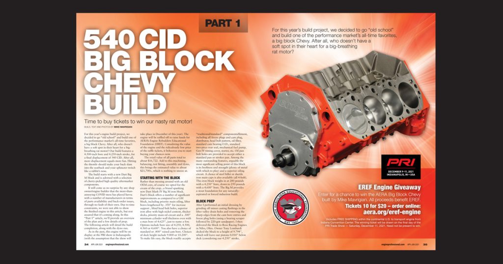
For this year’s engine build project, we decided to go “old school” and build one of the performance market’s all-time favorites, a big block Chevy. After all, who doesn’t have a soft spot in their heart for a big-breathing rat motor? Our build features a 4.500-inch bore and 4.250-inch stroke, for a final displacement of 540 CID. After all, more displacement equals more fun. Hitting the throttle should make your back slam into the seatback and your sphincter twitch like a rabbit’s nose.
The build starts with a new Dart Big M block and is adorned with a selection of cherry-picked high quality aftermarket components.
Read this article with all images in the digital issue of Engine Professional magazine https://engineprofessional.com/2021EPQ2/#p=36
It will come as no surprise by any shop owner/engine builder that the more-than-annoying COVID mess has played havoc with a number of manufacturers in terms of parts availability and back-order issues, through no fault of their own. Due to time constraints, we were not able to show the finished engine in this article, but rest assured that it’s coming along. In this “Part 1” article, we’ll provide an overview of the plan and a few details of prep. The following article will detail the build completion, along with the dyno run.
As in the past, this engine will be on display at the PRI show in Indianapolis (with the assumption that the show will take place in December of this year). The engine will be raffled off to raise funds for AERA’s Engine Rebuilders Educational Foundation (EREF). Considering the value of the engine and the ridiculously low price of the raffle tickets, it behooves you to start buying your chances now.
The retail value of all parts total to about $16,722. Add to this machining, balancing, test fitting, assembly and dyno, this brings the estimated value to about $21,700+, which is nothing to sneeze at.
STARTING WITH THE BLOCK
Rather than messing around with an old OEM core, of course we opted for the cream of the crop…a brand spanking new Dart Mark IV Big M iron block. Dart’s block offers a number of significant improvements as compared to a GM block, including priority main oiling, lifter bores lengthened by .350″ for increase support , blind head bolt holes, superior iron alloy with high nickel content, thicker decks, priority main oil circuit and a .300″ minimum cylinder wall thickness even with a max bore of 4.625″, just to name a few. Options include bore size of 4.250, 4.500, 4.560 or 4.600″. You also have a choice of standard or .400″ raised cam bore. Choices of deck height include 9.800 or 10.200″. To make life easy, the block readily accepts “traditional/standard” components/fitment, including all freeze plugs and cam plug, distributor, head bolt pattern, oil filter, standard cam bearing O.D., standard two-piece rear seal, mechanical fuel pump, Gen IV timing cover, starter, etc. Oil pan bolt holes are provided to accept either a standard pan or stroker pan. Among the many outstanding features, arguable the most significant selling point of this block is its beefiness and strength (plenty of metal with which to play) and a superior oiling circuit. A choice of steel billet or ductile iron main caps is also available (all 4-bolt). This iron block weighs in at 280 pounds with a 4.250″ bore, down to 250 pounds with a 4.600″ bore. The Big M provides a stout foundation for any naturally-aspirated or forced induction build.
BLOCK PREP
After I performed an initial dressing by grinding off minor casting flashings in the lifter valley drain holes and removing the sharp edges from the cam bore entries and freeze plug holes (using a bearing scraper followed by 220-grit sandpaper). I then delivered the block to Ross Racing Engines in Niles, Ohio. Owner Tony Lombardi decked the block to a height of 9.794″, which will leave our pistons 0.014″ below deck (considering our 4.250″ stroke, half stroke of 2.125″ plus rod length of 6.385″ plus piston CD of 1.270″, at a deck height of 9.794″, pistons at TDC will be 0.014″ below deck). We could have gone with a standard deck of 9.800″, but having pistons 0.020″ below deck seemed wasteful. Granted, we could have gone tighter, but our final deck height provides a bit of extra valve clearance for the “just in case” scenario.
Cylinders were bored by removing 0.006″ to obtain initial 4.497-inch bore diameter, followed by CNC honing on Tony’s new Rottler H85AX CNC honing station where final bore size was obtained at 4.500″ by removing a final 0.003″, using diamond stones followed by plateau honing with. Tony noted that his new Rottler machine cuts his block honing time in half as compared to his traditional honing machine. Honing and brush finishing was done with deck pates in place. This result provided 0.0045″ of piston to wall clearance. The Rottler machine is programmed for desired bore size, and the honing arm enters and finishes bore-by-bore automatically, providing a live data graph display of bore size and cylinder wall profile on the swing-out monitor. Tony then fitted our lifter bores, removing 0.0005″ to obtain a 0.0017-inch oil clearance for our Morel Black Mamba solid roller lifters (Morel’s John Callies recommends a lifter clearance of 0.0015 – 0.0017″).
All head deck threaded holes were cleaned and checked using a Goodson
7/16-14 thread chaser and then cleaned.
With the crank positioned on the upper main bearings, a rod and piston assembly (with rod bearings) was mocked up at each cylinder, carefully rotating the crank to check for rod big end to block clearance. All rod big end bolt heads to block pan rail area clearance was verified at 0.285 to 0.300″, providing more than enough room. I generally regard 0.050 – 0.060″ as a bare minimum.
With a rod and piston assembly test installed, crank counterweight to piston pin boss clearance was also checked. The tightest I found (at counterweights 1, 5 and 6) was 0.100″, again more than adequate (as I consider 0.060″ as a minimum). As Dart had already notched rod bolt clearance, no extra block clearancing was required.
With all crank/rod related clearances verified, it was time to have the block jet washed and meticulously cleaned by Jody Holtrey of Medina Mountain Motors, Creston, Ohio. For added security, I then scrubbed the oil galleys using Goodson’s high pressure cleaning tool kit, which is way cool. If you don’t already own one of these, get one. It features a billet machined handle with both air and water control, a stainless wand (18″ or 36″ length) and three cleaning rifle brushes (3/8, 1/2 and 5/8″). You can run the tool dry, or with water, or with compressed air, bot water and air together. The tip of the wand features spiral-oriented holes for water and/or air to create a strong swirl action.
Once the block was “clean,” I cleaned again, using extremely hot water and Dawn dishwashing liquid. This solution was routed through all holes and passages using an assortment of Goodson bore brushes, along with scrubbing the block exterior using a nylon bristle brush. This was followed by a hot rinse, immediately followed by a cold rinse (an effort to prevent quick surface oxidation) and blown dry with compressed air. Once absolutely dry, the block was masked and lightly primed with SEM self-etching primer. This was followed by a coat of Engine Pro gray primer and three coats of Engine Pro Chevy Orange. Our two earlier LS builds, as you may recall, were adorned with an all-black theme. For this go-around, I opted for traditional eye-popping Chevy Orange.
BLOCK PLUGS
The front and rear of our block’s main feed and lifter galley ports feature straight AN threads, not NPT. The front requires three 1/2″ O-ring AN plugs, and the rear takes two 1/2″ O-ring AN plugs and one 3/4″ O-ring AN plug (all were supplied with the block). These plugs are available from Dart (1/2″ is P/N 32892500; and the 3/4″ is P/N 32892750). Don’t assume that NPT plugs are used in these locations.
The forward end of the lifter valley features two NPT threaded holes that intersect with the lifter galleys. On hole requires a 1/4″ NPT plug and the smaller hole takes one 1/8″ NPT plug. The restrictor location is accessed by removing the 1/4″ plug. The block is tapped for 1/8″ NPT between the main oil feed and the lifter galley, if restriction is needed. Since we’re running a solid roller cam, we opted not to restrict.
The top rear left side of the block features a 1/2″ NPT port (to be used if running a remote oil filter) and a 1/4″ NPT port for oil pressure gauge installation.
Expansion plugs for the block sides and rear are standard 1-5/8″. The rear cam bore plug is also stock BBC size, 27/32″.
OIL FILTER ADAPTER SPECIAL NOTE
When installing a spin-on oil filter adapter to the block, Dart notes that the 5/16-18 mounting bolts must be 1-1/4″ overall length (note that this actually refers to threaded shank length). Dart emphasizes the importance of paying attention in order to provide 1/2″ of thread length to engage into the block. Regardless of bolt head height, the objective is to allow 1/2″ of thread depth in the block. Just be aware of this. The underhead length I used for the Melling adapter was 1.25″, with loc washers.
CRANK, RODS AND PISTONS
Our stroker crank (Scat 4-454-4250-6385 is a forged unit from Scat, featuring a 4.250″ stroke and 2.200″ rod journals and 2.749″ main journals, and a snout diameter of exactly 1.600″. Our H-beam forged steel rods are also from Scat, P/N 2-454-6385-2200A at a center-to-center length of 6.385″. I measured each rod, and length was spot-on-the-money. The floating pin diameter is 0.990″. Note that this crank requires “narrow” rod bearings in order to clear the generous rod journal fillets (Clevite CB743HN is an example).
During clearance checking I measured all of our Scat crank’s main journals spot-on at 2.749″, noting zero taper on all journals. With main bearings and main caps installed, I set our bore gauge at zero at each bearing location and individually checked oil clearance with the bore gauge checking our micrometer, obtaining a pleasing 0.003″ oil clearance at each main bearing location (0.0025 – 0.003″ is an acceptable standard for BBC). I also measured all rod journals at 2.200″. Again, each rod journal was exactly at 2.200″ with no taper. Scat really did a nice job on this crank. All fillets were nicely radiused, and all oil holes were edge-free with subtle chamfers and lead-in paths.
Pistons are forged aluminum slugs P/N IC516 from United Engine & Machine’s Icon line, featuring 10cc domes and anti-friction-coated skirts, with oil holes at the oil ring lands and full-float .990″ Trend wrist pins.
• Crank stroke 4.250
• Connecting rod length 6.385
• Piston CD 1.270 (0.990 floating pins)
Each wrist pin is secured with a single Trend spiral lock (supplied with the pistons) at each end of each pin.
CHECKING CRANK THRUST
Once main bearing oil clearance was verified, I applied CMD 3 to all bolt threads and underheads. I final-installed all main caps and fully seated all caps, then backed off the bolts and re-snugged to about 10 ft-lbs. I then knocked the crank fore/aft in order to obtain main cap register and checked crank thrust at 0.007″. All bearings were then coated with Royal Purple Max Tuff, and cocked the rear main upper and lower seal halves offset, with a dot of RTV on each exposed seal end. With all caps hand-snug, the crank was knocked fore/aft again. All caps were then torqued to 15 ft-lb and thrust was again verified at 0.007″. All cap bolts were then torqued to 30, then 50, then 65, then to a final 100 ft-lbs (with thrust verified after each step). She “spins like butta.”
ROD BEARING CLEARANCE
As noted earlier, all Scat crank rod journals measured exactly 2.200″ with no variation.. The Goodson micrometer was locked in at 2.200″ and secured to my Goodson micrometer stand. With a pair of MAHLE Clevite CB743 HN standard bearings fitted to a rod, with the ARP 2000 7/16″ x 1.600″ rod bolts torqued to 70 ft-lbs, I used my Goodson bore gauge to establish a zero reading on=f the installed bearings. Placing the bore gauge onto the mic, an oil clearance of 0.002″ was observed. I then swapped out the lower rod bearing shell for a CB 743HXN, and observed an oil clearance of 0.0025″, which I decided to incorporate. All rods will be fitted with a standard upper bearing and 1X lower bearing. During final assembly, all rod bolts will be tightened while monitoring stretch (Scat recommends a max stretch of 0.0062″ for the 7/16 x 1.6 ARP 2000 rod bolts).
Note: Take the time to read the instructions supplied with aftermarket rods. Torque recommendations and max rod bolt stretch specs will differ depending on the size and type of rod bolts. For instance, rods equipped with 7/16″ bolts may feature ARP 8740 or 2000 series bolts, at shank lengths of 1.400″, 1.500″, 1.600″ or 1.800″. 7/16″ x 1.400″ ARP 8740 bolts may require torque of 64 ft-lbs with max stretch of 0.0046″, while 7/16″ x 1.600″ ARP 2000 bolts may call for 70 ft-lbs and max stretch of 0.0062”. Bolt diameter, type of material and length all factor into required tightening specs. Bolt heads are marked with series type, and thread diameter and length are easily checked. Pay attention.
CAMSHAFT INSTALL
Once the block was absolutely clean and painted, we installed a set of coated cam bearings supplied by Dart. A test fit of the cam revealed an easy finger spin. During cam installation, I coated the journals with Royal Purple Max Tuff synthetic assembly lube, which provides excellent lubricity with great cling. A roller cam must be positioned to minimize endplay, since roller cam lobes are “flat” with no taper (a non roller cam lobes feature a slight taper to force the cam rearward, preventing it from walking forward). If the roller cam features a step in the nose, a retainer plate may be installed to prevent excess forward walk. If the cam nose does not feature a step, a thrust button is required that installs into the cam gear center hole and contacts the cam nose and provides a forward thrust limit at the rear of the top timing cover. Since our cam is non-stepped, we used a roller thrust button included in the Comp 3-piece timing cover set. Per the instructions with Comp’s timing cover kit, cam endplay/thrust should be in the 0.005 – 0.010″ range. Shims are used to adjust the thrust button placement. With the cam installed, insert the thrust button and the timing cover. The lower cover section features a 1/8″ NPT hole for dial indicator access to the bottom of the cam gear face. Using a long flat blade screwdriver, gently walk the cam rearward via one of the lifter bores, zero the indicator, and walk the cam forward to observe play. If play is excessive, remove the thrust bearing and insert spacer shims (included in the kit) and try again. Shim thicknesses include 0.005, 0.010 and 0.020″. Fine tune until you gain acceptable endplay. We managed to set ours at 0.007″. Once thrust was set, the three 1/4-20 SHCs were removed and a retainer plate that captures the thrust button was installed. Socket head cap screws are provided in order to clear the thrust button (since hex head screws prevent access with a socket wrench). Because our Cloyes Hex-A-Just timing set features an eccentric bushing at the cam nose dowel location that allows cam advance/retard adjustment, I had to drill a hole in the retainer plate to clear the hex adjuster. I then opened that hole fully at the outside to reveal the timing reference dots on the cam gear. The Cloyes set also features a thrust bearing (Torrington) that seats into a recess of the rear of the cam gear. If cam timing adjustment is needed, simply loosen the three gear-to-cam mounting screws, adjust the eccentric and retighten the screws to 25 ft-lbs with medium strength thread locker.
In combination with our 1.7:1 Harland Sharp roller rockers, our solid roller billet cam from Comp features an effective 0.715″ lift at both intake and exhaust, with duration (@0.050) of 276 intake and 282 exhaust. Firing order features a 4/7 timing swap.
Why is the 4/7 swap firing order beneficial? Changing the firing order offers several benefits. With a common pin V8 crankshaft, it is impossible to eliminate having adjacent cylinders fire subsequent to one another in the sequence. A 4/7 firing order moves the hot spot from the 5/7 cylinders up to the more-forward 4/2 cylinders. This move aids in cooling in an engine that features a front-mounted water pump.
Also, there are main bearing benefits in terms of reducing harmonics and improved oiling. Theoretically, you’ll see better bearing life and less indications of scuffing when moving to a 4 and 7 swap. Again, firing pairs is what we are trying to change. The focus is on pairs that fire on the same pin, thereby focusing the force on the adjacent crank main bearings. Moving this to the back of the engine seems to be a good idea because, even with a crank dampener, the drive train is much better at dampening these forces than a small mass on the end of the crank. When we consider the power that can be gained with lighter weight, lower viscosity oils, bearing life becomes not only a durability, but also a power concern.
Finally, changing the firing order is one of the best ways to change the cylinder to cylinder fuel and air distribution in the engine. Just like throws on the crank and cylinders next to each other in the block or head, we have to deal with ports next to each other and across from each other asking the manifold for air right after one another. This creates a very dynamic system in the manifold plenum where pressure waves of air (and also fuel in a wet manifold) are moving from front to back and side to side. Changing the firing order definitely changes how the ports interact.
LIFTERS
Our solid roller lifters are from Morel, their top-of-the-line Black Mamba series. These feature centered pushrod cups, DLC coating, offset tie bar links, an O.D. of 0.842″ and +.300″ taller gen VI style for BBC, required to accommodate the taller increased-support lifter bores in the Dart block. Morel specifies lifter bore oil clearance at 0.0015 – 0.0017″. These high-strength, lightened lifters feature a solid roller bearing axle instead of needle bearings for added durability. As mentioned earlier, Tony Lombardi at Ross Racing Engines machined all lifter bores by an added 0.0005″ to achieve an oil clearance of 0.0017″.
CYLINDER HEADS
Our head selection involves a pair of Dart’s Pro 1 CNC aluminum heads, featuring 121cc chambers, 325cc intake volume, 2.250″ intake valves, 1.880″ exhaust valves, with raised .300″ exhaust port locations, stock intake port locations, 24-degree intake valves and 15-degree exhaust valves. Springs are 1.625″ diameter, 275 lbs @ 2.00″ (for .850” max lift).
Just as a verification check, I measured combustion chamber volumes at each chamber. Dart lists these CNC heads as having 121cc chambers. Using our Goodson CCB-Kit measurement kit and burette, each chamber checked out at 121cc as advertised (yet another testament to Dart’s attention to detail and the use of precision CNC machining).
To secure the heads, we’re using a set of ARP head studs, P/N 235-4328. This set features 12-point nuts. An alternative is 235-4118 (same kit but with 6-point nuts) or Dart P/N 66120014-20. Nuts will be torqued to 70 ft-lb. Sealing will involve a pair of Fel-Pro MLS gaskets P/N 1077041 with a compressed thickness is 0.041″, gasket bores at 4.640″ and compressed volume of 11.4cc. Unfortunately at the time of this writing, the gaskets were on back order. We’ll discuss final head installation in the next article (Part 2).
ROCKERS
For this build, we opted for Harland Sharp aluminum full-roller rockers at a ratio of 1.7:1, selected from their Diamond Series, P/N SD2001. These full roller forged aluminum rockers clear 1.650″ diameter valve springs and offer a lightweight design, eliminating as much as 100 grams from the valvetrain moving mass. The design is also low profile, providing added valve cover clearance for those who may be running stock type valve covers.
PUSHRODS and PTV
Naturally, we’ll measure for correct pushrod length once we perform mock assembly. Once specific intake and exhaust length is determined, we’ll order a set of 3/8 Nitro Black pushrods from Engine Pro (diameter to be determined based on available clearance). While stock BBC pushrod length is 8.275″ intake and 9.250″ exhaust, Dart notes that with their Pro 1 heads, intake pushrod length generally requires about 0.200″ more and exhaust about 0.250″ more. With checking pushrods mocked up in the ballpark (I have not yet adjusted for rocker roller sweep on the valve tips, as I’m waiting for the back-ordered Fel-Pro head gaskets), I did an early/preliminary piston to valve clearance check. With the cam adjuster bushing set at “zero”, with intake opening and exhaust closing, we checked at 10-degrees BTDC and 10-degrees ATDC, measuring about 0.225″ clearance at the intake and about 0.250″ at the exhaust valve, so we know we don’t have a too-tight clearance issue (thankfully). Once the final-length pushrods are installed and the rockers are properly adjusted, we’ll naturally perform a final check, and will likely advance the cam a few degrees in order to decrease intake PTV clearance. The Cloyes adjustable cam gear bushing allows up to a 6-degree change, so we can likely decrease intake clearance by roughly 0.060″ if needed. Again, at this early point of test fitting, we’ve only performed a cursory “rough” PTV check, just to get an idea of our ballpark clearance.
CRANK BALANCE
Balancing was performed by Craig Haslem, owner of RPM Engine & Machine, Medina, OH. We initially weighed reciprocating components, including pistons, pins, pin locks, rings, connecting rods and rod bearings. Balance correction was a relatively easy task, only requiring weight to be removed from the front and rear counterweights, with no need for heavy metal.
Our bobweights were finalized at 2269.40 grams.
- Rod total weight 797 g
- Rod big end 550.40 g
- Rod small end 246.60 g
- Rod bearing 48.30 g
- Piston 590.40 g
- Piston pin 175.10 g
- Pin locks 4.40 g
- Piston rings 37.70 g
- Support rail 9.80 g
- Oil 8.00 g
- Reciprocating percentage 50%
- Rotating percent 100%
HARMONIC BALANCER
Our 8″ Fluidampr P/N 800101 features a bore diameter of 1.5990″, providing an interference fit of 0.001″ to our Scat crank snout, which features a diameter of 1.600″. This registers to a single 3/16″ key. The damper features a black zinc finish and CNC engraved timing marks from 50 BTDC to 10 ATDC. Additional timing marks include 90, 180 and 270 degrees. Weight is 16.3 lbs, with a rotating weight of 10.9 lbs. With anti-seize paste lightly applied to the snout and bore, the damper was drawn onto the snout using a Moroso damper installer tool.
INTAKE MANIFOLD/CARBS
Just for the fun of it we decided to employ an “old school” approach with a Weiand hi-rise dual-carb intake, P/N 1985, mated to a pair of Holley 950 cfm mechanical secondary carbs. The intake manifold, featuring rectangular ports, is a two-piece affair. The upper plenum mates to the lower with four 5/6-18 socket head cap screws and mil-spec flat washers. With the upper in place along with the supplied gaskets, the screws are inserted from top to bottom (the holes in the upper are open with no threads…the lower features female threads). Weiand recommends applying Loctite Pro-Lock (red) thread compound to the screw threads. Torque each screw to 18-20 ft-lb.
The 80805-RDX carbs (4150 series) feature aluminum construction for a 38% weight savings, contoured venture inlets for balanced airflow, outward-placed air bleeds, integrated idle bypass, dual 30cc accelerator pumps, 20% increased fuel bowl capacity and 8AN O-ring threaded inlets. And of course, added bling with red anodized metering plates and baseplate.
Note: due to somewhat restricted space at the rear of the Weiand hi-rise intake manifold, an HEI-size distributor will not clear (re the large diameter). In order to gain the needed clearance, we chose MSD 8570 Pro Billet distributor. Since we’re running an MSD crank trigger setup, we simply locked out the distributor’s advance. As far as gear-to-gear compatibility is concerned, the MSD distributor is already fitted with a cast iron mellonized gear, which is compatible any cam gear, so there was no need to change the distributor gear.
The only issue we ran into was that of carb linkage clearance for the rear carb, as the bottom of the lever arm (for return spring) contacted the top of the plenum. We’ll add a 1″ spacer between each carb and the manifold. This requires using ARP 400-2402 carb studs measuring 2.7″ in overall length.
The Holley carbs will be controlled using a Holley dual carb linkage kit, P/N 4022. Unfortunately, due to common back-order issues throughout the industry, the linkage kit wasn’t available at the time of this article, but will be installed prior to our dyno run, which will be featured in an upcoming issue.
IGNITION
Our ignition system is 100% MSD, including Pro Billet distributor P/N 8570, crank trigger kit, plug wires, coil and ignition control. Since we’re running a crank trigger ignition, the distributor requires a lock-out for advance. While MSD offers a distributor specifically for crank trigger use (P/N 84697) with no mechanical advance, due to the space constraints of our tunnel ram intake, we needed a distributor head that was smaller in diameter to clear the intake manifold. The 8570 distributor fills the bill nicely. We simply had to lock the advance out of the distributor. Our distributor also features a slip collar, allowing us to fine-tune the height placement for the distributor for ideal gear mesh to the cam gear. Note: The MSD distributor is factory-equipped with a cast iron mellonized gear, which is compatible with our billet steel cam, so there was no need to swap out for a bronze or polymer gear.
Read this article with all images in the digital issue of Engine Professional magazine https://engineprofessional.com/2021EPQ2/#p=36