Our 2022 build commemorates AERA’s 100th Anniversary.
Here’s Part 1 to tease your tastebuds.
By Mike Mavrigian
Since 2022 celebrates AERA’s 100th anniversary, we wanted to do something “special.” After much discussion and debate, we opted to combine old school with new school, using the iconic Ford Flathead 8BA block as the foundation for this year’s build.
The build starts with a Ford Flathead 8BA block (1949-1953). We plan to overbore and increase stroke (final overbore to be determined once we sonic check cylinder wall thickness). We’ll likely go +0.125″ or +0.155″, and stroke (via a Scat forged crank) will be 4.125″, with Scat forged H-beam rods at 7.000″ length. Again, depending on overbore, final displacement will be 284 or 289 CID. All new aftermarket components will be utilized. In addition to rebuilding the bottom end (short block status), we’ll incorporate a few modern-day systems including Edelbrock heads and intake manifold, MSD ignition and fuel injection utilizing either throttle body injection or direct port.
The exterior treatment (from a visual standpoint) will dress our little flattie to the nines with extreme detail…the block exterior will be deburred, smoothed, primed and painted to a glass-like finish. The finished engine will be dyno’d for performance results, and will be on display and raffled off at the 2022 PRI show in Indianapolis.
Read this article with all images in the digital issue of Engine Professional magazine https://engineprofessional.com/2022EPQ2/#p=38
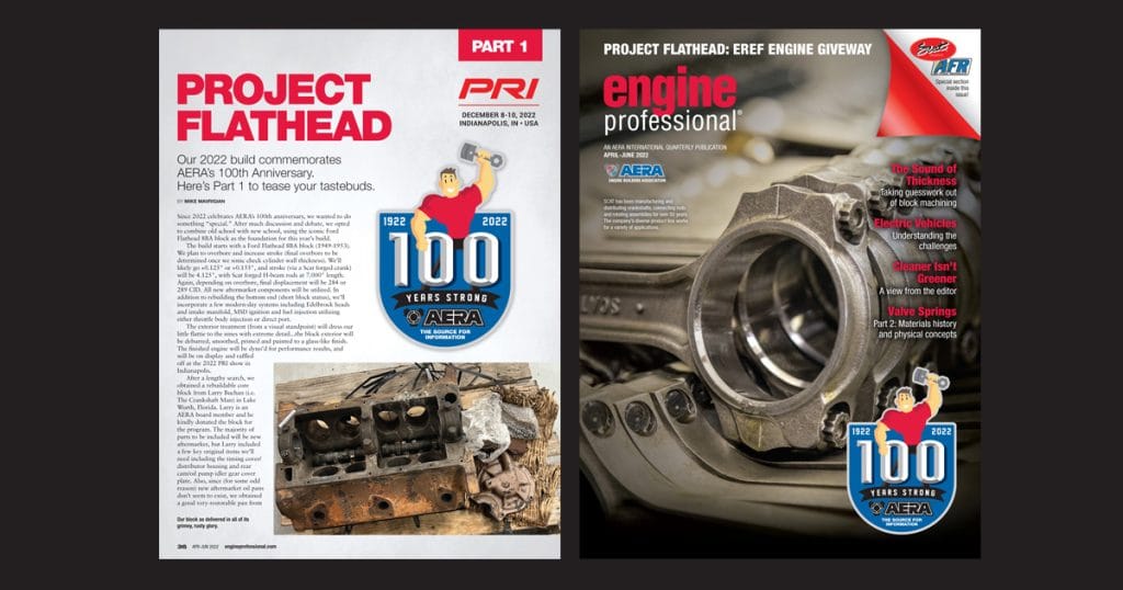
After a lengthy search, we obtained a rebuildable core block from Larry Buchan (i.e. The Crankshaft Man) in Lake Worth, Florida. Larry is an AERA board member and he kindly donated the block for the program. The majority of parts to be included will be new aftermarket, but Larry included a few key original items we’ll need including the timing cover/distributor housing and rear cam/oil pump idler gear cover plate. Also, since (for some odd reason) new aftermarket oil pans don’t seem to exist, we obtained a good very-restorable pan from Bill Ketch of K&B Street Rods, Dover, New Jersey, who also graciously donated to the cause.
The block arrived sans crank, rods and pistons but still had the valves and cam in place. As expected, removing the valve keepers, retainers, springs, valves, guides and lifters proved to be a bit of a chore, as you might imagine with an original block that has been sitting in the shadows for perhaps some sixty years or more.
After soaking the valves, guides and lifters with penetrating oil for a full two days, I began disassembly. Using an old-school flathead valve “pickle fork” tool, I compressed each valve spring, grabbing just below the retainer to reveal the valve locks. With the valve raised up out of the block, I smacked the old valve head with a brass hammer to knock the keepers out. While each valve was still raised beyond the block deck, I inserted a pair of needle nose pliers onto the valve stem just below the valve head to keep the valve raised. I then was able to nudge/twist/pull the valve out. The valve spring was then compressed and nudged sideways to pop free of the guide. To be honest, in a few locations, I cheated. I used a die grinder with a small cutoff wheel to cut the springs apart, which made it quite a bit easier to then remove the springs. With the springs out of the way, I then drove the guides down into the lifter valley by about 0.150″ to allow removal of the guide C-clip using a broad drift. The guide was then removed by fully driving it out of its bore into the lifter valley. By rotating the cam to raise the lifter up, I grabbed the lifter with pliers and rotated and pulled up, persuading it out. The procedure was followed for each valve location. The process went fine except for number 4 exhaust lifter, which was absolutely stuck in the raised position (there always has to be at least one stubborn brat to give you a headache). To remove that stuck lifter, I turned the block upside down and nudged the lifter up and out of its bore using a brass drift and hammer, contacting the bottom of the lifter adjacent to the cam lobe. With all lifters out of the way, the old cam, though somewhat stubborn, was removed (she simply did not want to leave home….but with penetrating oil, rotation and nudging, she finally gave up the ghost and wiggled out). I’m sure that’s the first time that cam saw daylight in 69-74 years.
The only component left was the rear oil pump intermediate gear, which was simply stuck. Luckily, the rear face of the gear assembly features a 3/8-16 threaded hole. I first installed a 3/8-16 bolt and tried rotating it but she wouldn’t budge (no surprise). I then tried using a slide hammer, with jaws gripping behind the bolt head washers, to no avail. Finally, I made a simple pulling tool using a 6″ long x 2.5″ wide x 0.250″-thick piece of steel flat stock. I drilled a center hole at 7/16″ to allow the 3/8″ bolt engaged to the gear to pass through. I then drilled and tapped one hole at each end of the flat stock for 3/8-16. I installed a 3/8-16 bolt into these threaded holes, with the bolt heads facing toward the block. With the two outer bolt heads resting against the block, I then tightened the bolt threaded into the gear. With no movement yet, I applied heat to the gear and continued to tighten. After repeated steps of heat and gradual tightening, the gear finally began to move and popped out, much to my delight.
A few exterior block plugs and fittings were removed (one ¼” NPT plug at the block front just above the cam bore, requiring a 5/16″ hex bit, a brass fitting on the left lower side of the block, a brass oil pressure fitting on the left upper bellhousing area and a square-head plug adjacent to the oil pressure fitting). At this point, the cam bearings can be removed and she’s ready for initial cleaning.
Bear in mind that any damage to valves, guides, springs, etc. was inconsequential, as all new components will be installed during assembly. In all (after the oil soak) I spent one entire day gutting the block of its valvetrain. I’m sure that anyone who has dealt with resurrecting old vintage rust-bucket blocks can empathize. Once the block was empty, off it went to be oven-baked and jet washed at Medina Mountain Motors, a local shop a mere one mile from our Birchwood Automotive shop, where test fitting, final assembly and photos will be performed.
The block was magnaflux checked for cracks and passed with flying colors. The only repair required appears to be a small pinhole on the left rear bank where the water jacket is open to the lifter valley. This will be remedied by sealing the pinhole using Loctite Liquid Steel (2-part sealer). The pinhole area will be cleaned/prepped with muriatic acid. Once the acid does its job, the area will be rinsed/neutralized and allowed to dry. The Liquid Steel compound will then be applied on both sides of the pinhole. This is a very minor (and common) glitch that will eliminate the concern (considering that the block is about 70 years old, we’re not complaining).
While we’re still finalizing the build plan in terms of fuel delivery, as noted earlier, the primary aspects will include a Scat forged crank featuring a 4.125″ stroke, Scat 7.000″ forged rods, and perhaps +0.155″ forged pistons (for an as-now-planned displacement of 289.47 CID), a Melling oil pump, Fluidampr crank pulley/damper, a Comp flat tappet Thumpr series cam and adjustable lifters, ARP fasteners, Edelbrock cylinder heads and MSD ready-to-run distributor. Remaining components to be selected soon. While we plan to go with +0.155″ pistons, the final cylinder bore size will be selected once we sonic check the cylinder walls. Initial block deck height measured at 10.455″, prior to deck resurfacing. In combo with our 4.125″ stroke and 7.000″ rods, piston compression height will be 1.374″. If we go with +0.125″ oversize pistons, bore size will be 3.3125″, providing us with 284 CID. If we go with our planned +0.155″ oversize pistons, bore size will be 3.342″, with 289 CID.
The Comp cam is P/N 41-600-7 (Comp’s Mutha Thumpr series), which should provide a tasty and choppy idle with 364/350 lift, advertised duration of 267/299 and 107 LSA. In addition to using aftermarket parts that feature vastly improved metallurgy, tighter tolerance machining and design, we also plan to include a few “newer technology” components, so stay tuned for a few surprises.
For more information about this year’s EREF Engine Giveaway, go to AERA.org/eref-engine.
Read this article with all images in the digital issue of Engine Professional magazine https://engineprofessional.com/2022EPQ2/#p=38